Aerial Work Platform with Compact Air Compressor

a technology of air compressor and work platform, which is applied in the direction of lifting devices, lifts, transportation and packaging, etc., can solve the problems of reducing efficiency at the worksite, increasing costs for stand-alone units, and requiring considerable space for the tank of reciprocating air compressors

Inactive Publication Date: 2009-09-03
ILLINOIS TOOL WORKS INC
View PDF26 Cites 20 Cited by
  • Summary
  • Abstract
  • Description
  • Claims
  • Application Information

AI Technical Summary

Problems solved by technology

Unfortunately, the operator must independently setup, move, and generally control both the AWP and the stand-alone units, thereby reducing efficiency at the worksite.
The stand-alone units also increase costs due to the need for their own power sources (e.g., engine), control systems, enclosures, wheels, and so forth.
Unfortunately, the reciprocating type air compressor requires considerable space to accommodate the tank.
Without the tank, the reciprocating type air compressor does not provide a generally constant air pressure to the operator due to the reciprocating mechanism, e.g., piston in cylinder.
Unfortunately, many air-driven tools require a generally constant air pressure.

Method used


Image

  • Aerial Work Platform with Compact Air Compressor
  • Aerial Work Platform with Compact Air Compressor
  • Aerial Work Platform with Compact Air Compressor

Examples


Embodiment Construction

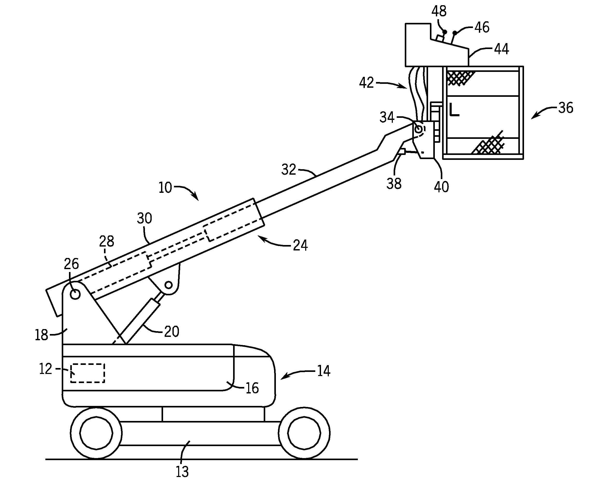
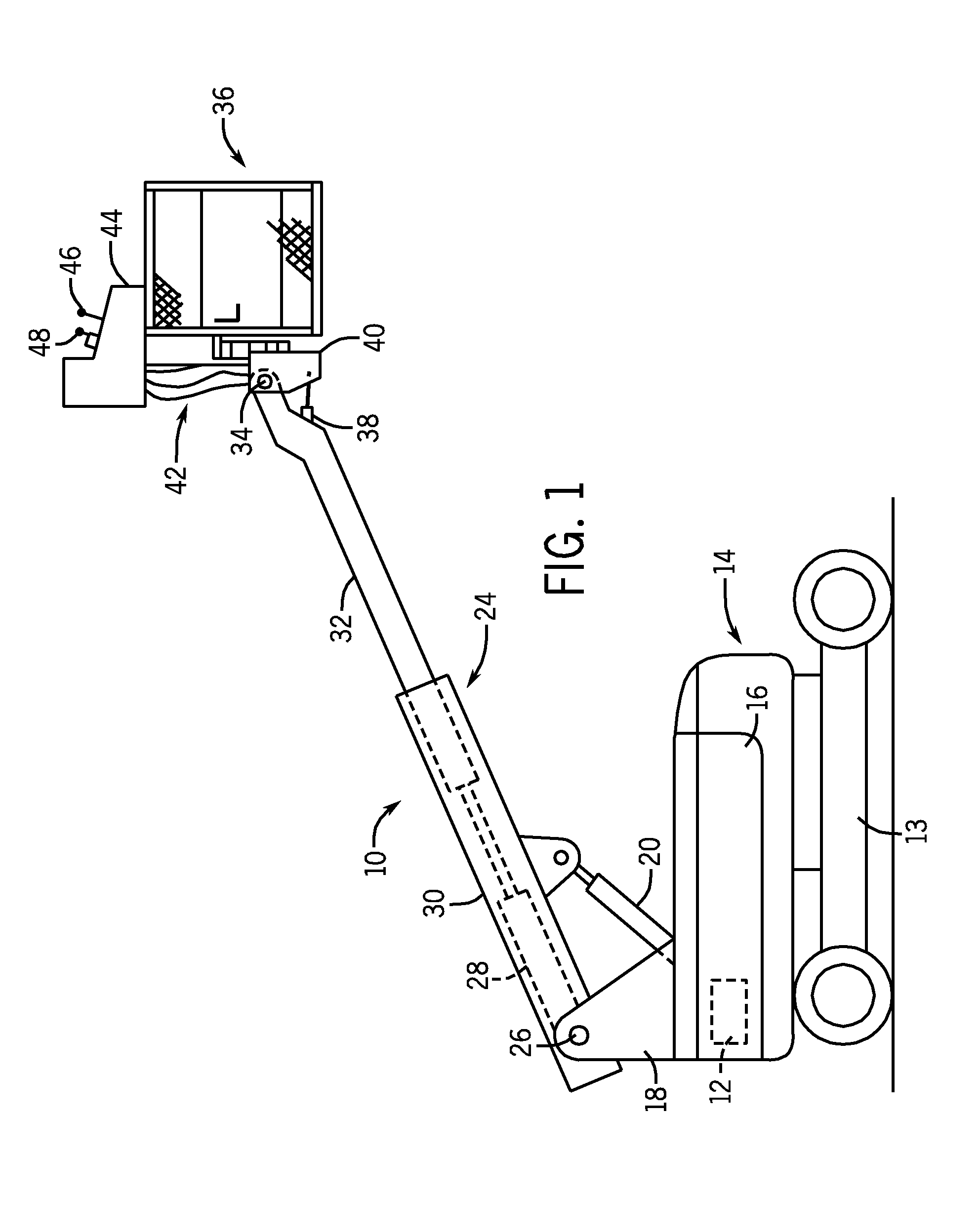
[0008]Turning now the drawings, FIG. 1 illustrates an aerial work platform (AWP) 10 including a rotary air compressor 12. Aerial work platform 10 also includes wheeled chassis 13 (e.g., chassis having four wheels) and aerial work platform base unit 14. As will be discussed in further detail below, aerial work platform 10 may provide various services or resources, such as compressed air and electric power, to an elevated worker. Various devices within AWP base unit 14, such as rotary air compressor 12, may provide these resources.

[0009]In the illustrated embodiment of FIG. 1, the rotary air compressor 12 may include a rotary screw compressor or other suitable compressor configured to supply a continuous flow of compressed air without the need for an intermediate storage tank. The rotary screw compressor 12 may include a type of gas compressor that has a rotary-type positive displacement mechanism. The rotary screw compressor 12 may include one or more screws, which rotate within an e...


PUM


Abstract

An aerial work platform, in one embodiment, includes a platform, including a hydraulic lift, and a base unit. The base unit includes a combustion engine and a hydraulic pump driven by the combustion engine. The hydraulic pump may be configured to drive the hydraulic lift. The base unit may also include a rotary screw type compressor, belt-driven by the combustion engine.

Description

BACKGROUND[0001]The invention relates generally to temporary lift platforms and, more particularly, aerial work platforms (AWPs).[0002]Aerial work platforms (AWPs) generally lift an operator to a desired location at a worksite. Often, the operator requires services, such as pressurized air and electricity. These services enable the use of air-driven tools and electrical tools. In many cases, the operator receives these services from stand-alone units on the ground, i.e., separate from the AWP. For example, the stand-alone units may include a stand-alone electrical generator and a stand-alone air compressor. Unfortunately, the operator must independently setup, move, and generally control both the AWP and the stand-alone units, thereby reducing efficiency at the worksite. The stand-alone units also increase costs due to the need for their own power sources (e.g., engine), control systems, enclosures, wheels, and so forth. Furthermore, the stand-alone air compressor generally includes...

Claims


Application Information

Patent Timeline
Patent Type & Authority Applications(United States)
IPC IPC(8): B66F9/22
CPCB66F11/046
Inventor BEESON, RICHARD
Owner ILLINOIS TOOL WORKS INC
Why Eureka
Try Eureka