Plasma display panel

a technology of display panel and plasma, which is applied in the direction of dielectric/insulating layer, gas discharge vessel/container, instruments, etc., can solve the problems of relatively high power consumption of conventional pdps, and achieve the effect of reducing the reactive power consumption of pdp

Inactive Publication Date: 2009-09-03
SAMSUNG SDI CO LTD
View PDF5 Cites 2 Cited by
  • Summary
  • Abstract
  • Description
  • Claims
  • Application Information

AI Technical Summary

Benefits of technology

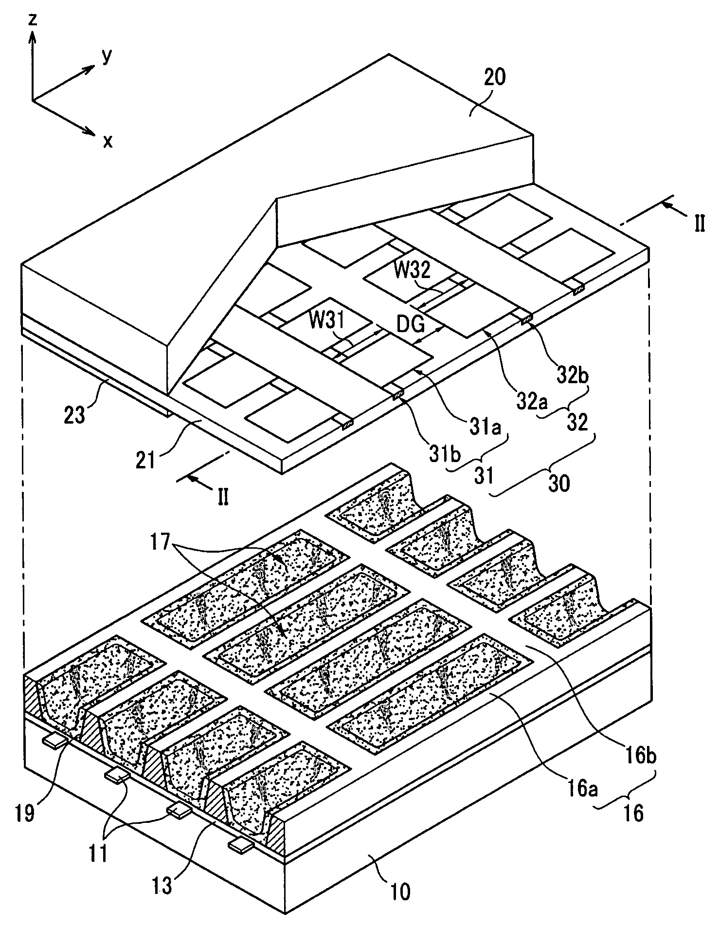
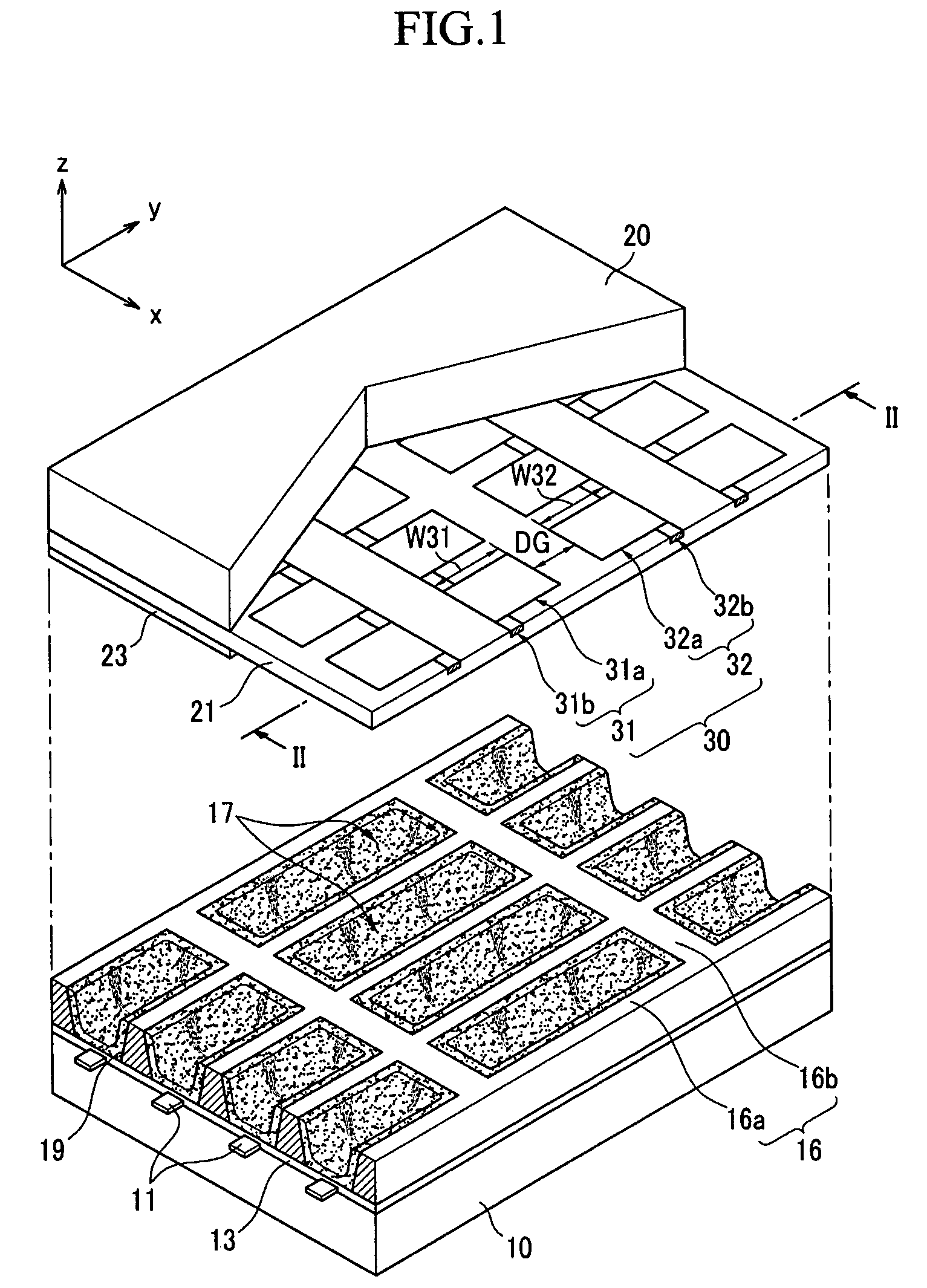
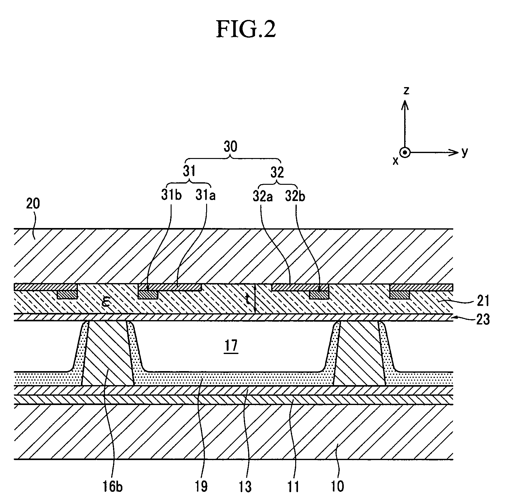
[0007]It is therefore a feature of an embodiment to provide a PDP having a dielectric layer structure with optimized dielectric constant with respect to thickness thereof capable of reducing reactive power consumption of the PDP.

Problems solved by technology

Conventional PDPs, however, may have relatively high power consumption.

Method used


Image

  • Plasma display panel
  • Plasma display panel
  • Plasma display panel

Examples


Embodiment Construction

[0014]Korean Patent Application No. 10-2008-0018368, filed on Feb. 28, 2008, in the Korean Intellectual Property Office, and entitled: “Plasma Display Panel,” is incorporated by reference herein in its entirety.

[0015]Example embodiments will now be described more fully hereinafter with reference to the accompanying drawings; however, they may be embodied in different forms and should not be construed as limited to the embodiments set forth herein. Rather, these embodiments are provided so that this disclosure will be thorough and complete, and will fully convey the scope of the invention to those skilled in the art.

[0016]In the drawing figures, the dimensions of layers and regions may be exaggerated for clarity of illustration. It will also be understood that when a layer or element is referred to as being “on” another layer or substrate, it can be directly on the other layer or substrate, or intervening layers may also be present. Further, it will be understood that when a layer is...


PUM


Abstract

A plasma display panel, includes rear and front substrates facing each other with a predetermined interval therebetween, barrier ribs between the rear and front substrates to define discharge cells, address electrodes on the rear substrate, the address electrodes extending in a first direction to correspond to the discharge cells, display electrodes on the front substrate, the display electrodes extending in a second direction to correspond to the discharge cells, the second direction intersecting the first direction, and a dielectric layer on the front substrate to cover the display electrodes, the dielectric layer having a dielectric constant of about 6 C2/N·m2 to about 7 C2/N·m2 and a thickness of about 16 μm to about 20 μm.

Description

BACKGROUND OF THE INVENTION[0001]1. Field of the Invention[0002]Example embodiments relate to a plasma display panel (PDP). More particularly, example embodiments relate to a PDP having reduced reactive power consumption.[0003]2. Description of the Related Art[0004]PDPs refer to display devices that may realize an image using gas discharge. That is, gas discharge in the PDP may generate plasma, thereby triggering emission of vacuum ultraviolet rays. The ultraviolet rays may excite phosphors to emit red, green, and blue visible light as the excited phosphors are stabilized. The PDPs may be self-emissive type display devices and, therefore, may have a quick response characteristic while overcoming a viewing angle limitation. Conventional PDPs, however, may have relatively high power consumption.[0005]The above information disclosed in this Background section is only for enhancement of understanding of the background of the invention and therefore it may contain information that does n...

Claims


Application Information

Patent Timeline
Patent Type & Authority Applications(United States)
IPC IPC(8): G09G3/28G09G3/288
CPCG09G3/288H01J11/38H01J11/12
Inventor KIM, GI-YOUNGPARK, HYOUNG-BINHWANG, EUI-JEONGCHO, YU-JEONG
Owner SAMSUNG SDI CO LTD
Why Eureka
Try Eureka