Anode carbon block for clamped anode conductive device

A technology of anode carbon block and conductive device, which is applied in the field of anode carbon block, can solve the problems of high cost, high contact resistance, uneven current density distribution of anode carbon block, etc., so as to reduce contact voltage drop, reduce assembly cost, and simplify assembly. The effect of process cost

Inactive Publication Date: 2011-05-11
高伟
View PDF0 Cites 2 Cited by
  • Summary
  • Abstract
  • Description
  • Claims
  • Application Information

AI Technical Summary

Problems solved by technology

[0003] A carbon bowl is constructed on the anode carbon block, and a cast phosphorus iron ring is used between the anode anode steel claw and the anode carbon block. The iron-carbon contact resistance of the iron ring is relatively large, and the average voltage drop is about 130mv; the second is that the phosphorus iron ring between the iron and carbon adopts the high cost of molten cast iron hot casting process; the third is the separation of the anode stub and the phosphorus iron ring, and the phosphorus iron ring The separation of the ring and the anode steel claw head adopts mechanical pressing or hammering process, and the cost is high; the fourth is that the current density distribution of the anode carbon block is uneven due to the deformation of the anode steel claw and the partial pouring of the phosphorus iron ring

Method used


Image

  • Anode carbon block for clamped anode conductive device
  • Anode carbon block for clamped anode conductive device
  • Anode carbon block for clamped anode conductive device

Examples


Embodiment 1

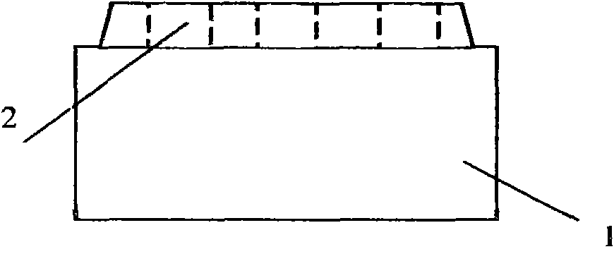
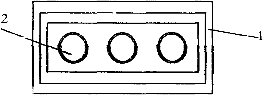
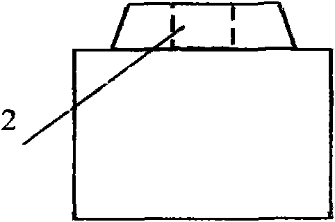
[0026] Embodiment one: the anode carbon block (1) for aluminum electrolytic cell clamping type anode conduction device of the present invention, such as image 3 Figure 4 As shown, the upper part of the carbon block (1) has a convex clamping platform (3) connected with the anode conductive fixture, and there is no such thing as the general-purpose anode carbon block (1), on the top of the carbon block (1). Set the cast carbon bowl (2) with phosphorus iron ring as figure 1 , figure 2 , image 3 As shown, the two sides of the convex clamping table (3) of the anode carbon block (1) for the clamping type anode conductive device are constructed with convex retaining walls (4 ). Two conductive side splints forming an anode conductive fixture between the convex retaining walls (4) on both sides and the convex clamping table (3) can be inserted and can be electrically connected to the lower clamping table (3). Recessed slots (5), such as Figure 4 , Figure 5 , Figure 6 Sho...


PUM


Abstract

The invention discloses an anode carbon block for a clamped anode conductive device. On the upper part of the anode carbon block, a circular carbon bowl for casting a phosphorus iron hoop by using rainwater is cancelled, and the upper part of the anode carbon block is provided with a convex clamping table in clamping connection with an anode conductive clamp; and the lateral surface of the convex clamping table on the upper part of the carbon block is provided with a lug boss retaining wall for preventing electrolyte from eroding the anode conductive clamp.

Description

technical field [0001] The anode carbon block involved in the present invention is mainly used in the production and preparation of the anode carbon block of the prebaked aluminum electrolytic cell and its application in the electrolytic cell. Background technique [0002] The cross-section of the general prebaked aluminum electrolytic cell anode anode carbon block is a rectangular upper rectangle, and the upper structure has several circular phosphorus iron rings pouring carbon bowls. By pouring phosphorus iron rings into the carbon bowls of the anode carbon block, Both the anode steel claw and the anode carbon block are interspersed with conductive load-bearing connections. [0003] A carbon bowl is constructed on the anode carbon block, and a cast phosphorus iron ring is used between the anode anode steel claw and the anode carbon block. The iron-carbon contact resistance of the iron ring is relatively large, and the average voltage drop is about 130mv; the second is tha...

Claims


Application Information

Patent Timeline
Patent Type & Authority Applications(China)
IPC IPC(8): C25C3/12
Inventor 高德金杨青高伟
Owner 高伟
Why Eureka
Try Eureka