Anode conducting clamping fixture
A conductive clip and anode technology, which is applied in the field of anode conductive clamping fixtures, can solve the problems of uneven current density distribution and high cost of anode carbon blocks, and achieve the effects of simplifying assembly process costs, reducing voltage drop, and reducing resistance power consumption.
- Summary
- Abstract
- Description
- Claims
- Application Information
AI Technical Summary
Problems solved by technology
Method used
Image
Examples
Embodiment 1
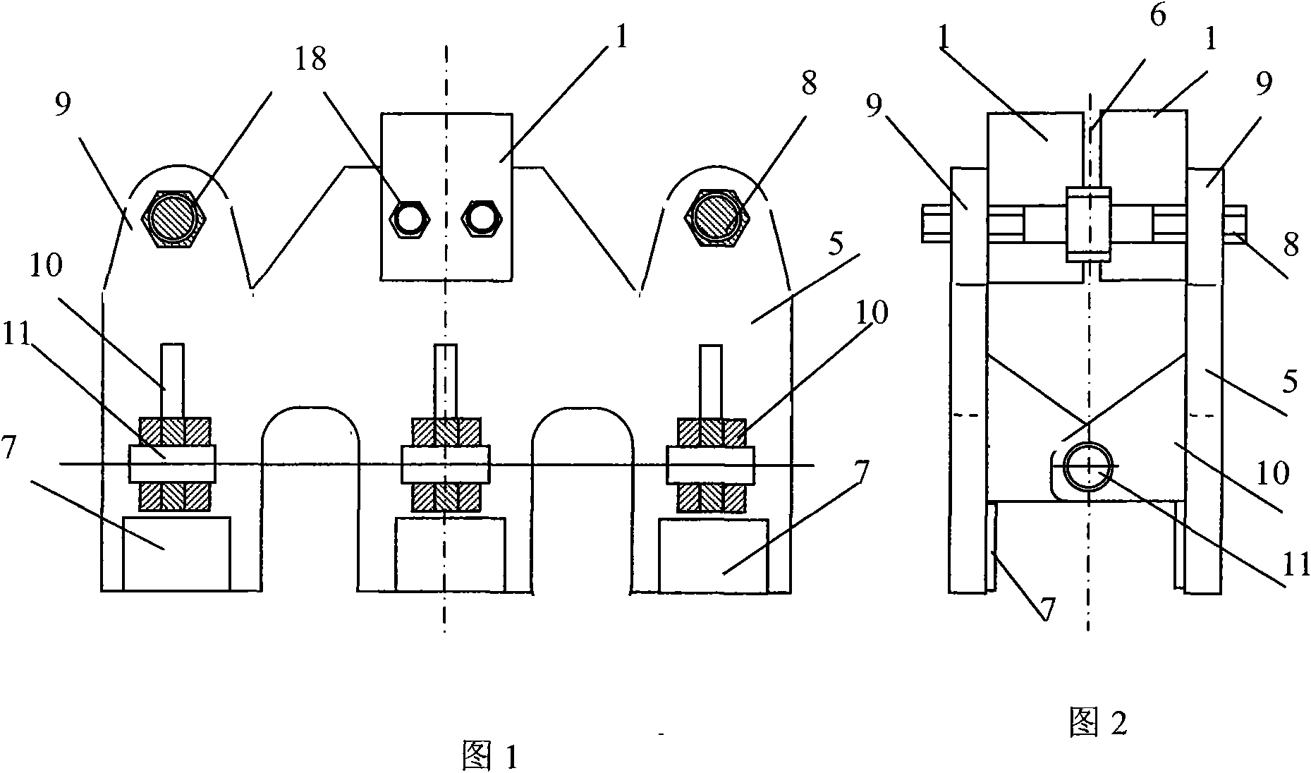
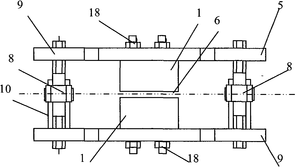
[0032] Embodiment 1: as figure 1 , figure 2 , image 3 As shown, the anode conductive clamp (2) is composed of two conductive side splints (5) arranged on both sides as the main components, and spiral supports (9 ), two-way adjusting screw rods (8) are arranged in the two spiral bearings (9), and a supporting hinged orifice (10) is respectively fixed and constructed on the lower inner parts of the two conductive side splints (5), and the hinged orifice is supported on both sides In (10), the pin shaft (11) is used for piercing; the inner side of the upper middle part of the conductive side splint (5) is electrically and tightly connected with the aluminum guide rod (1) with bolts; the lower end structure of the aluminum guide rod is used to open left and right fit the adjustment center seam (6).
[0033] When using the anode conductive clamping fixture (2) to connect the aluminum guide rod (1) and the anode carbon block boss (4) for conductive electrical connection, first ...
Embodiment 2
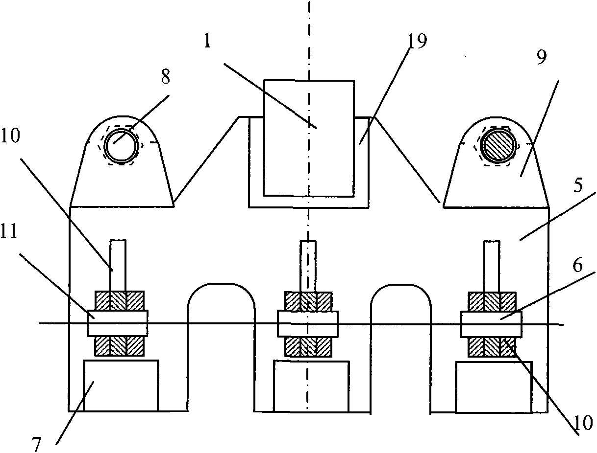
[0036] Embodiment 2: as Figure 4 Figure 5 Figure 6As shown, the anode conductive clamping fixture (2) is the same basic structure as that of embodiment 2 and embodiment 1, and the difference is that the middle and upper parts of the conductive side splints (5) on both sides of the anode conductive clamping fixture (2) and The connection of the aluminum guide rod (1) does not adopt the connecting bolt (18) to conduct the conductive clamping connection directly like the embodiment 1, but adopts the transition of the aluminum-steel metal connector (19) to carry out the welding conductive connection. The usage method of embodiment 2 is the same as embodiment 1.
Embodiment 3
[0037] Embodiment 3: as Figure 7 Figure 8 Figure 9 As shown, the anode conductive clamping fixture (2) is composed of two conductive side splints (5) arranged on both sides as the main components, and the conductive side splints (5) on both sides are for the anode carbon block boss (4 ) The clamping force adjustment device is a lifting and tensioning type, and its structure is: a top cover pinch plate (12) is buckled above the two conductive side splints (5), and a lifting shaft plate (12) is installed inside the top cover pinch plate (12). Screw rod (13), the lower end screw thread of lifting screw rod (13) is connected with spiral sleeve shaft (14); Two small pull rods (15) with hinged holes at both ends are installed on the spiral sleeve shaft (14); The inner lower side end of the conductive side splint (5) is respectively fixedly constructed with a hinged hole pull plate (17), and in the hole of the hinged hole pull plate (17) the other side of the small pull rod (15)...
PUM
 Abstract
Description
Claims
Application Information
 - R&D
- Intellectual Property
- Life Sciences
- Materials
- Tech Scout
- Unparalleled Data Quality
- Higher Quality Content
- 60% Fewer Hallucinations
Browse by: Latest US Patents, China's latest patents, Technical Efficacy Thesaurus, Application Domain, Technology Topic, Popular Technical Reports.
© 2025 PatSnap. All rights reserved.Legal|Privacy policy|Modern Slavery Act Transparency Statement|Sitemap|About US| Contact US: help@patsnap.com


