
Novel anode electric-conducting device for aluminum electrolytic cell

A technology for an aluminum electrolytic cell and a conductive device is applied in the field of a new type of anode conductive device for an aluminum electrolytic cell, which can solve the problems of uneven current density distribution, high cost, high resistance and the like of the anode carbon block, so as to simplify the assembly process cost and reduce the cost Voltage drop, the effect of reducing resistance power consumption

Inactive Publication Date: 2010-03-03
高德金
View PDF0 Cites 18 Cited by
  • Summary
  • Abstract
  • Description
  • Claims
  • Application Information

AI Technical Summary

Problems solved by technology

[0003] The current general-purpose aluminum electrolytic cell anode conductive device mainly has the following disadvantages: first, the iron-carbon contact resistance of the phosphorus-iron ring for connection between the anode steel claw and the anode carbon block is relatively large, and the average voltage drop is about 130mv; The phosphorus iron ring between the carbons adopts the hot casting process of molten cast iron, and the cost is relatively high. The third is that the separation of the anode butt and the phosphorus iron ring, and the separation of the phosphorus iron ring and the anode steel claw head adopts a mechanical pressing or hammering process, and the cost is relatively high. high
Fourth, the current density distribution of the anode carbon block is uneven due to the deformation of the anode steel claw and the partial pouring of the phosphorus iron ring.

Method used


Image

  • Novel anode electric-conducting device for aluminum electrolytic cell
  • Novel anode electric-conducting device for aluminum electrolytic cell
  • Novel anode electric-conducting device for aluminum electrolytic cell

Examples


Embodiment Construction

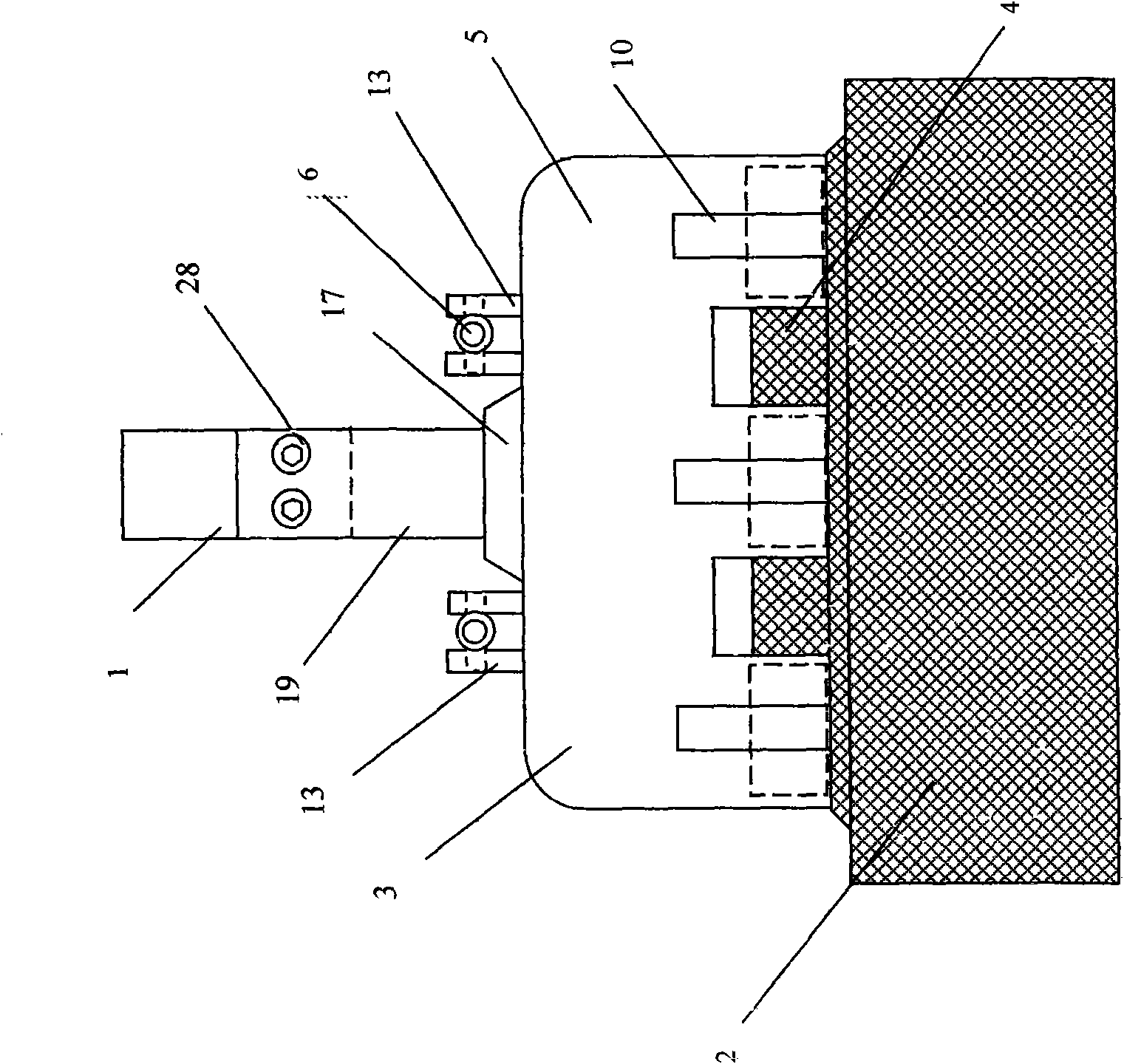
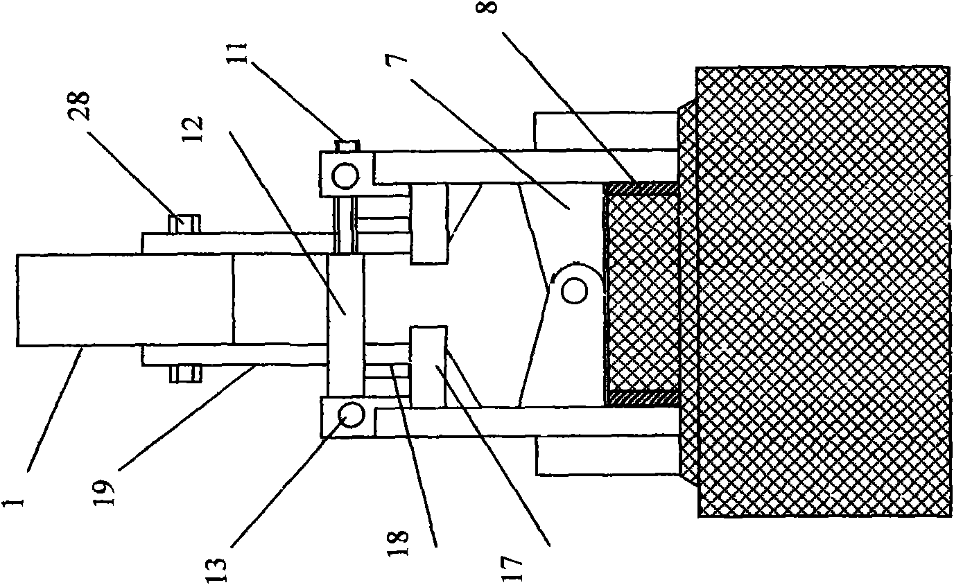
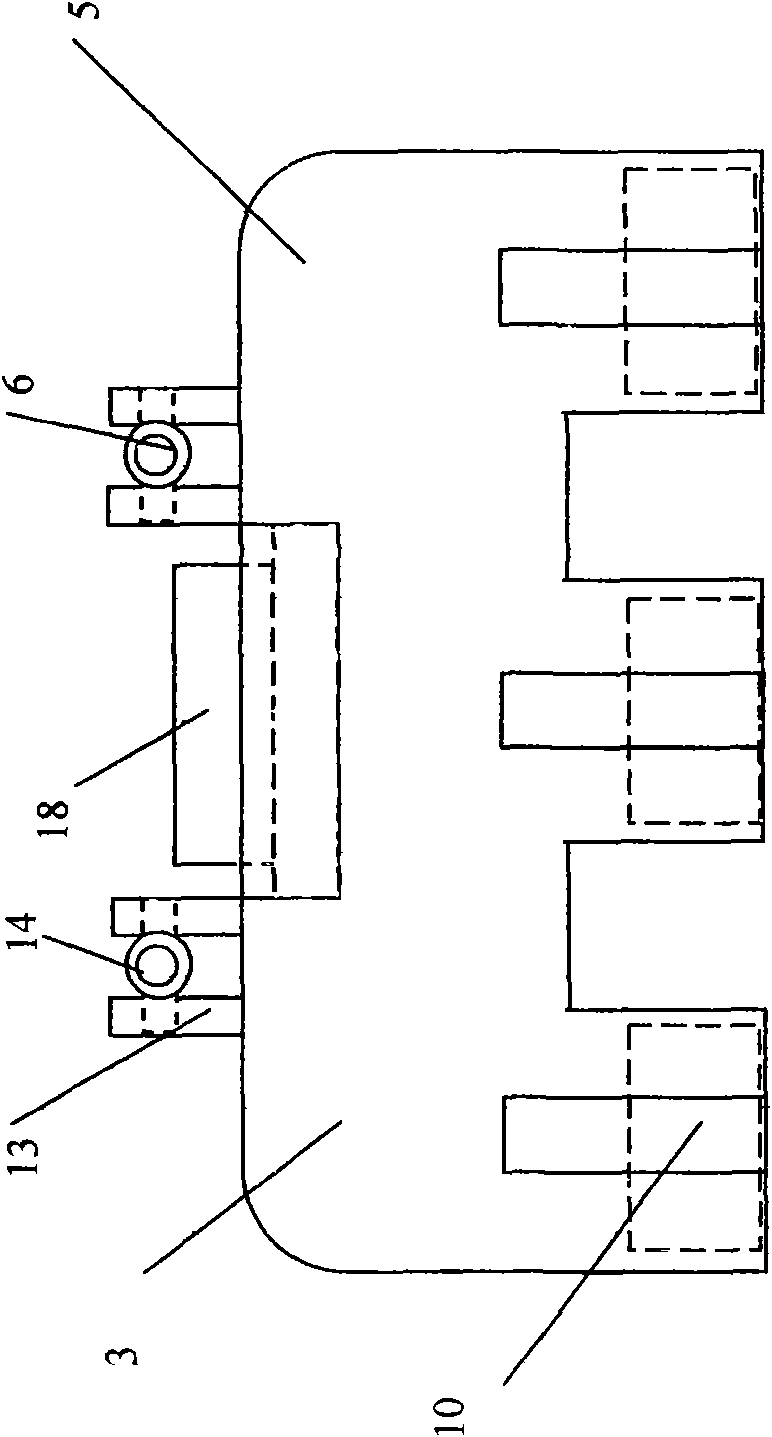
[0037] A novel aluminum electrolytic cell anode conductive device is composed of an aluminum guide rod, an anode carbon block clamping fixture and an anode carbon block 3 . The technical solution is: the aluminum guide rod 1 is connected with the clamping jig 3 of the anode carbon block, and the clamping jig 3 of the anode carbon block is clamped and connected with the upper boss 4 of the anode carbon block 2 . Such as figure 2 , Figure 18 , Figure 17 shown

[0038] A new type of aluminum electrolytic cell anode conduction device is composed of an aluminum guide rod, an anode carbon block clamping fixture 3 and an anode carbon block 2 with a boss 4 on the upper part. The aluminum guide rod 1 and the anode carbon block 3 use Anode clamping fixture 3 carries out conductive connection, such as figure 1 , figure 2 , Figure 16 shown.

[0039] In order to realize the connection between the anode clamping fixture 3 and the anode carbon block, on the top of the anode carbo...


PUM


Abstract

The invention relates to a novel anode electric-conducting device for an aluminum electrolytic cell, which comprises an aluminum guide rod, an anode carbon block clamp holder and an anode carbon blockand is characterized in that the aluminum guide rod is connected with the anode carbon block through the anode carbon block clamp holder, and the anode carbon block clamp holder is in clamping connection with a boss at the upper part of the anode carbon block. By adopting the novel anode electric-conducting device for the aluminum electrolytic cell, since the changed assembly method of the prioranode steel stub, the ferrophosphorus ring and the anode carbon block is cancelled, the current of the aluminum guide rod is transferred to the anode carbon block by adopting a copper-carbon transition joint method, the voltage drop of the anode electric-conducting device can be reduced, the resistance power consumption of the electric-conducting structure of the aluminum electrolytic cell is reduced, and simultaneously, the assembly process cost of the anode carbon block and the pressure-disengaging process cost of the residual anode are both simplified.

Description

technical field [0001] A new type of aluminum electrolytic cell anode conductive device is mainly used in the production of aluminum electrolytic cells, that is, the assembly of aluminum guide rods and anode carbon blocks. Background technique [0002] The current general-purpose aluminum electrolytic cell anode conductive device is mainly composed of aluminum guide rods, explosive welding sheets, anode steel claws, anode carbon blocks and phosphorus iron rings. The anode steel claws and anode carbon blocks are formed by casting phosphorus iron rings. Connection of anode carbon blocks to steel claw heads. The anode conductive device of the aluminum electrolytic cell is not only a conductive part, but also a load-bearing part, so firstly, it must have a low resistance, secondly, it must have a certain tensile strength, and thirdly, it must have a certain high temperature resistance. [0003] The current general-purpose aluminum electrolytic cell anode conductive device mainl...

Claims


Application Information

Patent Timeline
Patent Type & Authority Applications(China)
IPC IPC(8): C25C3/12C25C3/16
Inventor 高德金高伟
Owner 高德金
Learn More