Motor having stator made of soft magnetic powder material

a technology of soft magnetic powder and stator, which is applied in the direction of dynamo-electric machines, magnetic circuit shapes/forms/construction, supports/enclosements/casings, etc., can solve the problems of reducing productivity, increasing production costs, and inconvenient assembly process, so as to reduce production costs

Inactive Publication Date: 2007-05-24
DAEWOO ELECTRONICS CO LTD
View PDF6 Cites 7 Cited by
  • Summary
  • Abstract
  • Description
  • Claims
  • Application Information

AI Technical Summary

Benefits of technology

[0010] Accordingly, the present invention has been made keeping in mind the above problems occurring in the prior art, and an object of the present invention is to provide a motor having a stator made of soft magnetic powder material in which a process of assembling a cover to the stator is simple, and standard sizes such as the length of the space inside the motor can be easily changed, so that the covers and the stators thereof are compatible with products having different standard sizes, thus reducing the production costs.
[0011] Another object of the present invention is to provide a motor having a stator made of soft magnetic powder material which is constructed such that a cover can be easily coupled to the stator without requiring extra coupling members, so that the process of assembling the motor is simplified, thereby increasing productivity and reducing the cost of the assembly process and thus the overall production costs.

Problems solved by technology

Hence, the insert holes 11a, 12a and 13a of the stator 13 must be aligned all at the same time, thereby making the assembly process inconvenient and reducing the productivity.
Furthermore, the production costs are made increased due to the increased expenses for the extra coupling members B and N.
However, the conventional motor 10 is problematic in that, when it is required to change the standard size of the motor 10, such as the length and height of the inner space, the stator as well as the covers must be re-engineered.

Method used


Image

  • Motor having stator made of soft magnetic powder material
  • Motor having stator made of soft magnetic powder material
  • Motor having stator made of soft magnetic powder material

Examples


first embodiment

[0041] The operation and effect of the above-mentioned motor 100 having the stator made of soft magnetic powder material according to the present invention will be explained herein below.

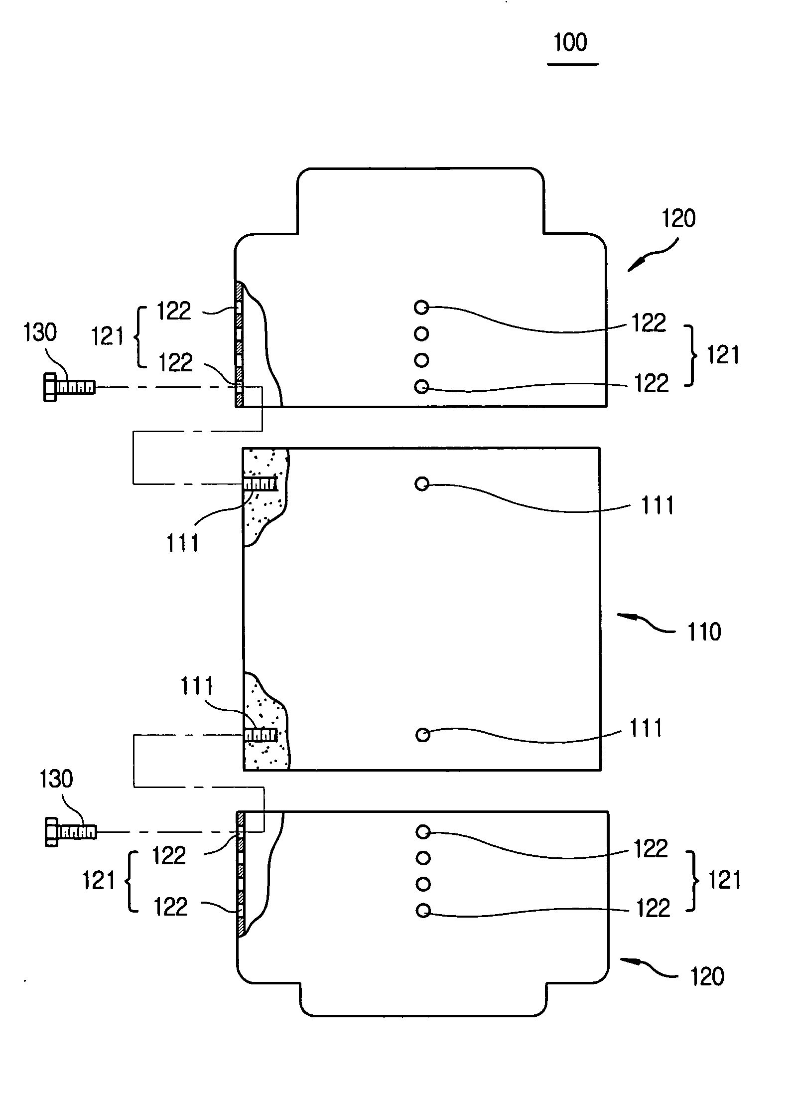
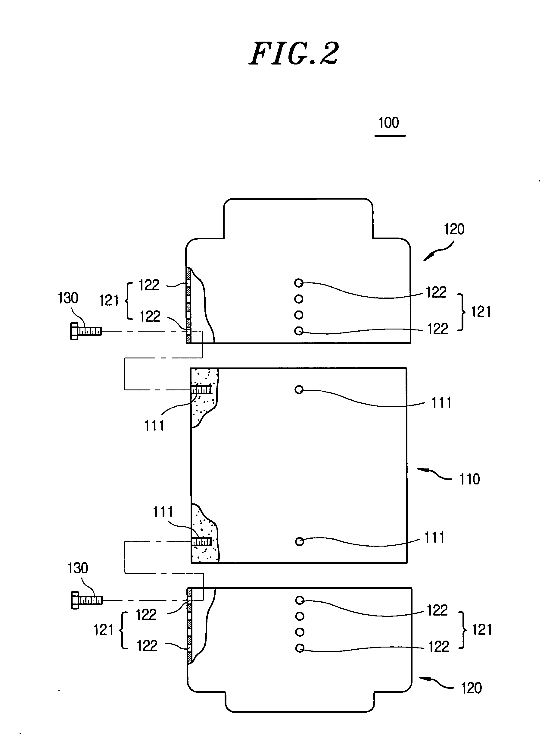
[0042] As shown in FIGS. 3A and 3B, the first covers 120 are fitted over the respective opposite ends of the first stator 110. Thereafter, the first coupling bolts 130 are tightened into the respective bolt holes 111 of the first stator 110 via the selected through holes 122 of the respective first coupling position adjustment parts 121, thus fastening the first covers 120 to the first stator 110. At this time, each first coupling bolt 130 passes through a selected one of the through holes 122 of the associated first coupling position adjustment part 121, so that the distance between the first covers 120 can be adjusted to change the length of the space in the motor 100.

[0043] In the case where the first coupling position adjustment parts 121, each of which has four through holes 122, are provided ...

second embodiment

[0045] In the second embodiment, the second stator 210 is formed by compressing soft magnetic powder using a compressing machine, so that the second coupling position adjustment parts 211 are formed in the circumferential outer surface of each end of the second stator 210 at positions spaced apart from each other at regular angular intervals.

[0046] Each second coupling position adjustment part 211 comprises a plurality of bolt holes 212, which are arranged in the longitudinal direction of the second stator 210.

[0047] The second stator 210 has the second coupling position adjustment parts 211 on respective opposite ends thereof, so that the positions at which the second cover 220 is fastened to each end of the second stator 210 using the second coupling bolts 230 are independently adjustable.

[0048] The motor 200 has the two second covers 220, which are fitted over respective opposite ends of the second stator 210. The through holes 221, each of which is aligned with the selected bo...

third embodiment

[0053] In the third embodiment, the third stator 310 is formed by compressing soft magnetic powder using a compressing machine, so that the coupling protrusions 311 can be relatively easily provided on the circumferential outer surface of each end of the third stator 310 at positions spaced apart from each other at regular angular intervals.

[0054] The motor 300 has the third covers 320, which are fitted over the respective opposite ends of the third stator 310. Furthermore, the coupling protrusions 311 are provided on the circumferential outer surface of each end of the third stator 310 such that each third cover 320 can be locked to the coupling protrusions 311 of each end of the third stator 310 using the third coupling position adjustment parts 321 at selected positions thereof.

[0055] As such, the two third covers 320 are fitted over the respective opposite ends of the third stator 310. The third coupling position adjustment parts 321 are provided on the circumferential surface ...


PUM


Abstract

A motor includes, a stator made of compressed soft magnetic powder, with a plurality of bolt holes formed around a circumferential outer surface of an end of the stator; a cover fitted over the end of the stator, with a plurality of coupling position adjustment parts provided around an end of the cover, the coupling position adjustment parts each comprising a plurality of through holes arranged in a direction in which the cover is fitted over the stator; and a plurality of coupling bolts, each of the plurality of coupling bolts being tightened into each of the bolt holes of the stator through the selected through hole of the associated coupling position adjustment part of the cover such that a position at which the cover is coupled to the stator is adjustable.

Description

FIELD OF THE INVENTION [0001] The present invention relates generally to motors having stators made of soft magnetic powder material and, more particularly, to a motor having a stator made of soft magnetic powder material which is constructed such that a cover is easily coupled to the stator without extra coupling members, thus simplifying a process of assembling the cover with the stator. BACKGROUND OF THE INVENTION [0002] As well known to those skilled in the art, motors are devices which convert electric energy into mechanical energy to provide rotating force. Such motors are widely used in industrial apparatuses as well as in domestic electronic products. Motors are classified into DC motors and AC motors. A typical motor includes a stator, around which a coil is wound, and a rotor, which is rotatably provided in the stator at a position spaced apart from the inner surface of the stator at a predetermined gap and is rotated by magnetic flux generated in the coil. [0003] Meanwhil...

Claims


Application Information

Patent Timeline
Patent Type & Authority Applications(United States)
IPC IPC(8): H02K5/00H02K1/12
CPCH02K1/02H02K1/185
Inventor CHA, YOUNG-NAMSHIN, NAM-CHUL
Owner DAEWOO ELECTRONICS CO LTD
Why Eureka
Try Eureka