Battery module having improved connection structure of sensing wire harness and assembly method thereof

a technology of sensing wire harness and battery module, which is applied in the direction of cell components, sustainable manufacturing/processing, and final product manufacturing, etc., can solve the problems of poor space utility, high production cost, and limited reduction of production cos

Active Publication Date: 2022-07-26
LG ENERGY SOLUTION LTD
View PDF31 Cites 0 Cited by
  • Summary
  • Abstract
  • Description
  • Claims
  • Application Information

AI Technical Summary

Benefits of technology

[0028]According to the present disclosure, assembly process costs may be reduced by simplifying a bonding process between a cell lead and a voltage sensing wire harness.
[0029]Also, since a separate connection metal and a fixing structure thereof may be omitted by directly welding a cell lead and a wire harness, material costs may be reduced and space utility may be increased.
[0030]Also, by disposing lead plates forming a cell lead to overlap each other and welding a connecting terminal directly on the lead plate, the cell lead may be prevented from being deformed by heat generated during welding.

Problems solved by technology

In the battery module where the plurality of cells are gathered, safety and operation efficiency are adversely affected when an event, such as an overvoltage or an overcurrent, occurs in some cells, and thus a unit for detecting voltage abnormality or the like is required.
However, when the PCB 12 and the bus bar 14 are used as such, the bus bar 14, i.e., a separate metal, needs to be separately designed and manufactured, and then mounted on the PCB 12, and thus production costs may be high.
Also, since a space for inserting and disposing the bus bar 14 at the bottom of the cell lead 11 needs to be secured, space utility is poor.
However, such a method requires a separate sensing bus bar as described above, and thus reducing of production costs may be limited.
Also, since a process of laser-welding the sensing bus bar to the cell lead, and a process of bending a compressed piece formed on the sensing bus bar and pressing the compressed piece to one end of the wire to be connected thereto need to be accompanied, large process costs are still required.

Method used


Image

  • Battery module having improved connection structure of sensing wire harness and assembly method thereof
  • Battery module having improved connection structure of sensing wire harness and assembly method thereof
  • Battery module having improved connection structure of sensing wire harness and assembly method thereof

Examples


Embodiment Construction

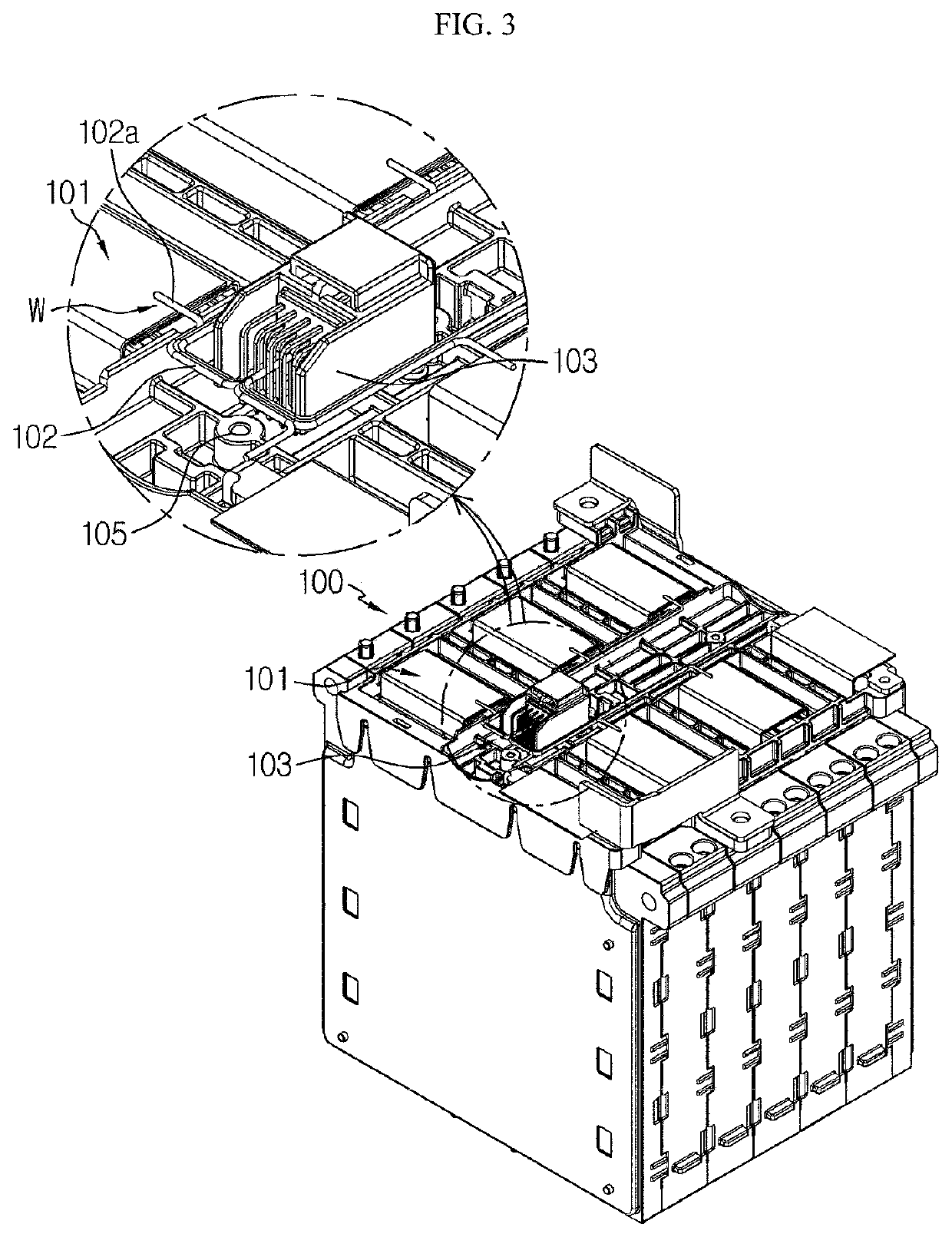
[0039]FIG. 3 is a partial enlarged perspective view of a structure of a battery module according to a preferable embodiment of the present disclosure, and FIG. 4 is a partial exploded view of FIG. 3.

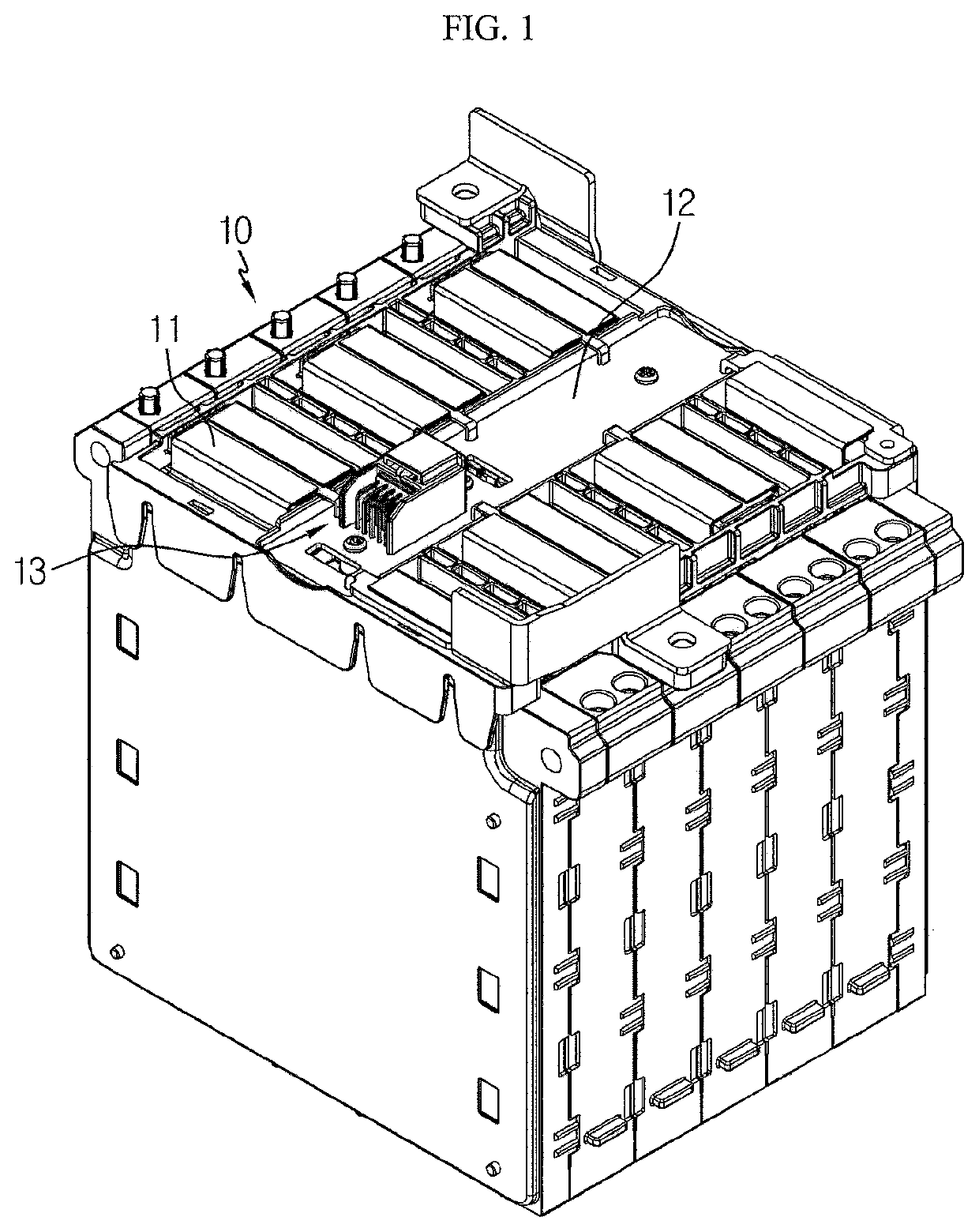
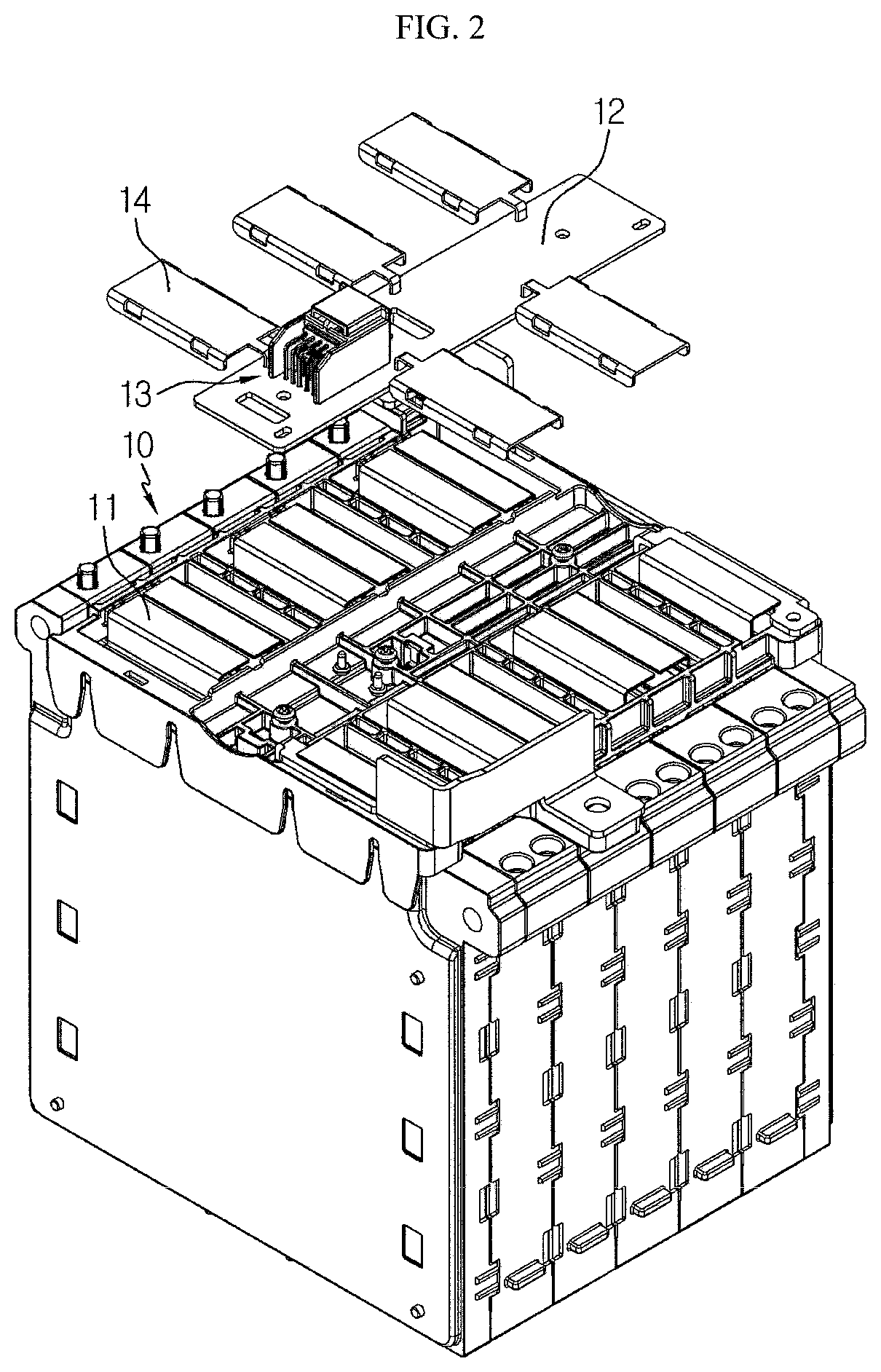
[0040]Referring to FIGS. 3 and 4, a battery module according to a preferable embodiment of the present disclosure includes a cell assembly 100 in which a plurality of cells are arranged, a sensing wire harness 102 disposed on a top of the cell assembly 100 and directly welded to a cell lead 101, and a connector 103 fixed to a body of the cell assembly 100 and connected to the sensing wire harness 102.

[0041]In the cell assembly 100, the plurality of cells are arranged in one direction at a predetermined interval, and the cell lead 101 is drawn out from each cell. Each cell has a thin plate shaped body, and preferably, is configured by a pouch type secondary battery. The plurality of cells are arranged in one direction of the cell assembly 100 to substantially form a stacked structure. A p...


PUM

PropertyMeasurementUnit
thermal expansionaaaaaaaaaa
lengthaaaaaaaaaa
structureaaaaaaaaaa

Abstract

Provided is a battery module including: a cell assembly in which a plurality of cells are arranged at a predetermined interval, wherein each of the plurality of cells includes a cell lead; a sensing wire harness disposed around the cell lead and including a connecting terminal corresponding to the cell lead, wherein the connecting terminal is directly bonded to the cell lead; and a connector connected to the sensing wire harness by being fixed at one side of the cell assembly.

Description

TECHNICAL FIELD[0001]The present application claims priority to Korean Patent Application No. 10-2016-0071204 filed on Jun. 8, 2016 in the Republic of Korea, the disclosure of which is incorporated herein by reference.[0002]The present disclosure relates to a battery module and an assembly method thereof, and more particularly, to a battery mode having an improved connection structure between a cell and a voltage sensing wire harness, and an assembly method thereof.BACKGROUND ART[0003]Generally, a battery module has a structure in which a plurality of cells are gathered through series and / or parallel connection. Such a battery module is manufactured in a structure including a cell assembly in which a plurality of cells are generally arranged in one direction and are substantially stacked on each other.[0004]In the battery module where the plurality of cells are gathered, safety and operation efficiency are adversely affected when an event, such as an overvoltage or an overcurrent, o...

Claims


Application Information

Patent Timeline
Patent Type & Authority Patents(United States)
IPC IPC(8): H01M8/24H01M6/42H01M50/502H01R4/30H01M10/48H01M50/20H01M50/211H01M50/516H01M50/517
CPCH01M50/502H01M10/48H01M10/482H01R4/30H01M50/20Y02E60/10H01M50/516H01M50/517H01M50/211Y02P70/50
Inventor LEE, GANG-USEONG, JUN-YEOB
Owner LG ENERGY SOLUTION LTD
Why Eureka
Try Eureka