Power switching circuit

a power switching circuit and circuit technology, applied in the direction of electronic switching, emergency protective circuit arrangement, pulse technique, etc., can solve the problem of preventing the power switching circuit from being damaged, and achieve the effect of accurate avoiding the situation

Inactive Publication Date: 2009-09-03
RENESAS ELECTRONICS CORP
View PDF23 Cites 25 Cited by
  • Summary
  • Abstract
  • Description
  • Claims
  • Application Information

AI Technical Summary

Benefits of technology

[0016]The power switching circuit according to an exemplary embodiment of the present invention includes a short circuit detector which detects a short circuit condition of the output current detection terminal and outputs a short circuit control signal for stopping the output transistor or limiting the current output. This enables to accurately avoid the situation in which an overcurrent

Problems solved by technology

Furthermore, when detecting an overcurrent flowing into the output transistor, the protection system needs to block the output transistor or reduce the output current.
That is, when using the techniques disclosed in Japanese Unexamined Patent Applicati

Method used


Image

  • Power switching circuit
  • Power switching circuit
  • Power switching circuit

Examples


first exemplary embodiment

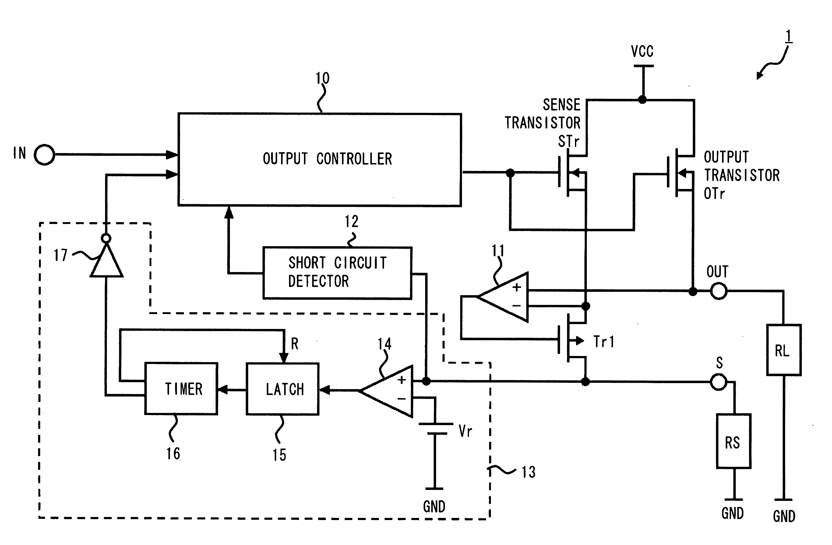
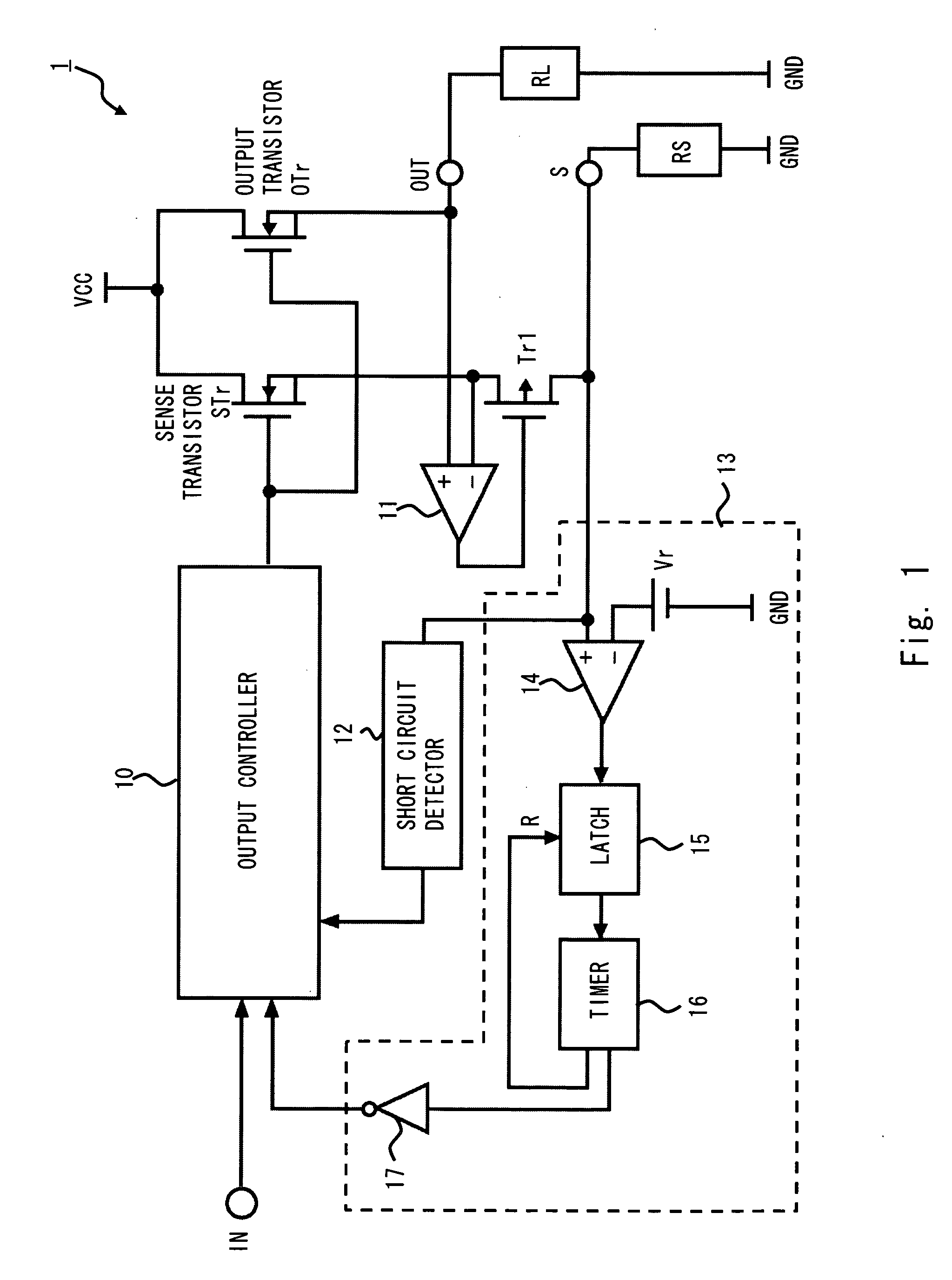
[0033]An exemplary embodiment of the present invention is described hereinafter with reference to the drawings. The block diagram of a power switching circuit 1 according to this embodiment is shown in FIG. 1. As shown in FIG. 1, the power switching circuit 1 includes an output controller 10, an amplifier 11, a short circuit detector 12, an overcurrent detector 13, a transistor Tr1, a sense transistor STr, an output transistor OTr, an input terminal IN, an output terminal OUT and an output current detection terminal S. Moreover, a load RL, which is a load circuit, is connected between the output terminal OUT and a ground terminal GND. A current sense resistor RS is connected between the output current detection terminal S and the ground terminal GND.

[0034]The output controller 10 outputs an output control signal which controls the conducting state of the output transistor OTr according to an input signal input via the input terminal IN. Moreover, when receiving an overcurrent detect...

second exemplary embodiment

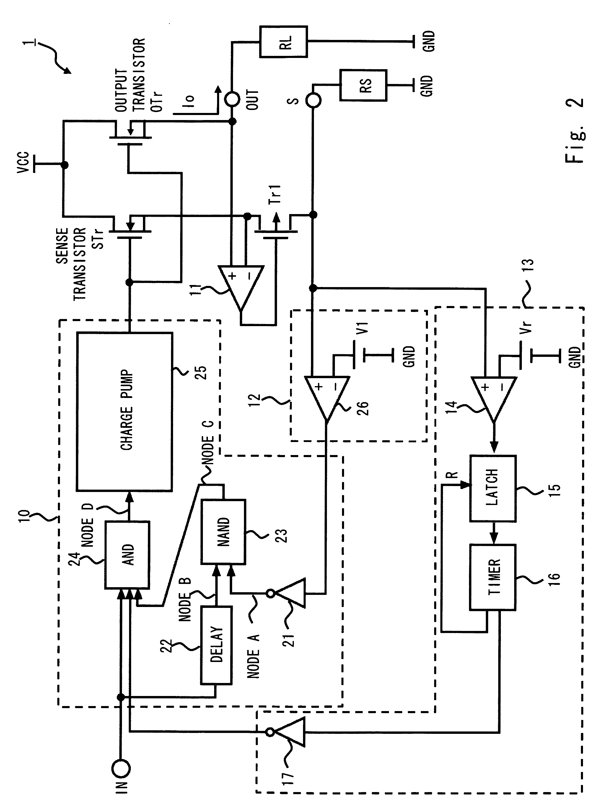
[0052]The second exemplary embodiment is another aspect of the output controller 10 and the short circuit detector 12 of the first exemplary embodiment. In the second exemplary embodiment, the power switching circuit includes an output controller 10a and a short circuit detector 12a, which have different aspects from the output controller 10 and the short circuit detector 12. The block diagram of a power switching circuit 2 according to the second exemplary embodiment is shown in FIG. 5.

[0053]The output controller 10a includes an AND circuit 24 and a charge pump circuit 25. The AND circuit 24 outputs an AND operation result of an input signal which is input from the input terminal IN and an overcurrent detection signal which is output by the overcurrent detector 13 to the charge pump circuit 25 as an enable signal. The charge pump circuit 25 outputs an output control signal according to the state of the enable signal as with the first exemplary embodiment.

[0054]The short circuit det...

third exemplary embodiment

[0062]The third exemplary embodiment shows another aspect of the output controller 10 and the short circuit detector 12 of the first exemplary embodiment. In the third exemplary embodiment, a power switching circuit includes an the output controller 10b and a short circuit detector 12b which have different aspects from the output controller 10 and the short circuit detector 12. The block diagram of a power switching circuit 3 according to the third exemplary embodiment is shown in FIG. 9.

[0063]The output controller 10b includes an AND circuit 24 and a charge pump circuit 25. The AND circuit 24 outputs an AND operation result of an input signal which is input from the input terminal IN, an overcurrent detection signal which is output by the overcurrent detector 13 and a short circuit control signal (node H) which is output by the short circuit detector 12b to the charge pump circuit 25 as an enable signal. The charge pump circuit 25 outputs an output control signal according to the s...


PUM


Abstract

A power switching circuit according to an exemplary embodiment of the present invention includes an output transistor connected between a power supply terminal VCC and an output terminal OUT, an output controller which controls a conducting state of the output transistor according to an input signal, a sense transistor having a gate commonly connected with the output transistor, which detects an output current flowing into the output transistor, an output current detection terminal in which a detection voltage is generated according to the output current detected by the sense transistor and a short circuit detector which detects a short circuit condition of the output current detection terminal according to the detection voltage and stops the output transistor or limits the output current.

Description

BACKGROUND[0001]1. Field of the Invention[0002]The present invention relates to a power switching circuit including an output current detection terminal for detecting an output current that flows into an output transistor.[0003]2. Description of Related Art[0004]Power supply switching circuits mounted between a power supply and a load circuit are often used for controlling a current flowing from the power supply into the load circuit in order to reduce the power consumption of the system. In a power switching circuit, generally an output transistor is connected between a power supply and a load circuit. Then, by operating the output transistor as a switch, the current flowing from the power supply into the load circuit is controlled.[0005]In such a power switching circuit, if an overcurrent flows into the output transistor due to a defect in the load circuit, a protection system is mounted for detecting the current and reducing or blocking an output current so as to protect the powe...

Claims


Application Information

Patent Timeline
IPC IPC(8): H02H3/24
CPCH03K17/284H03K17/0822H03K2217/0027
Inventor MITSUDA, TSUYOSHI
Owner RENESAS ELECTRONICS CORP
Why Eureka
Try Eureka