Magnetic Beacon Guidance System

Inactive Publication Date: 2009-09-03
SPECK NEIL
View PDF7 Cites 48 Cited by
  • Summary
  • Abstract
  • Description
  • Claims
  • Application Information

AI Technical Summary

Benefits of technology

[0031]The system may include a switching arrangement for switching the relative orientation

Problems solved by technology

Due primarily to cumulative systematic errors introduced by the measurement systems, an ellipse of uncertainty is created.
As a result, it a very hit and miss affair to cause the lateral hole to intersect the borehole and, to date, re

Method used


Image

  • Magnetic Beacon Guidance System
  • Magnetic Beacon Guidance System
  • Magnetic Beacon Guidance System

Examples


Embodiment Construction

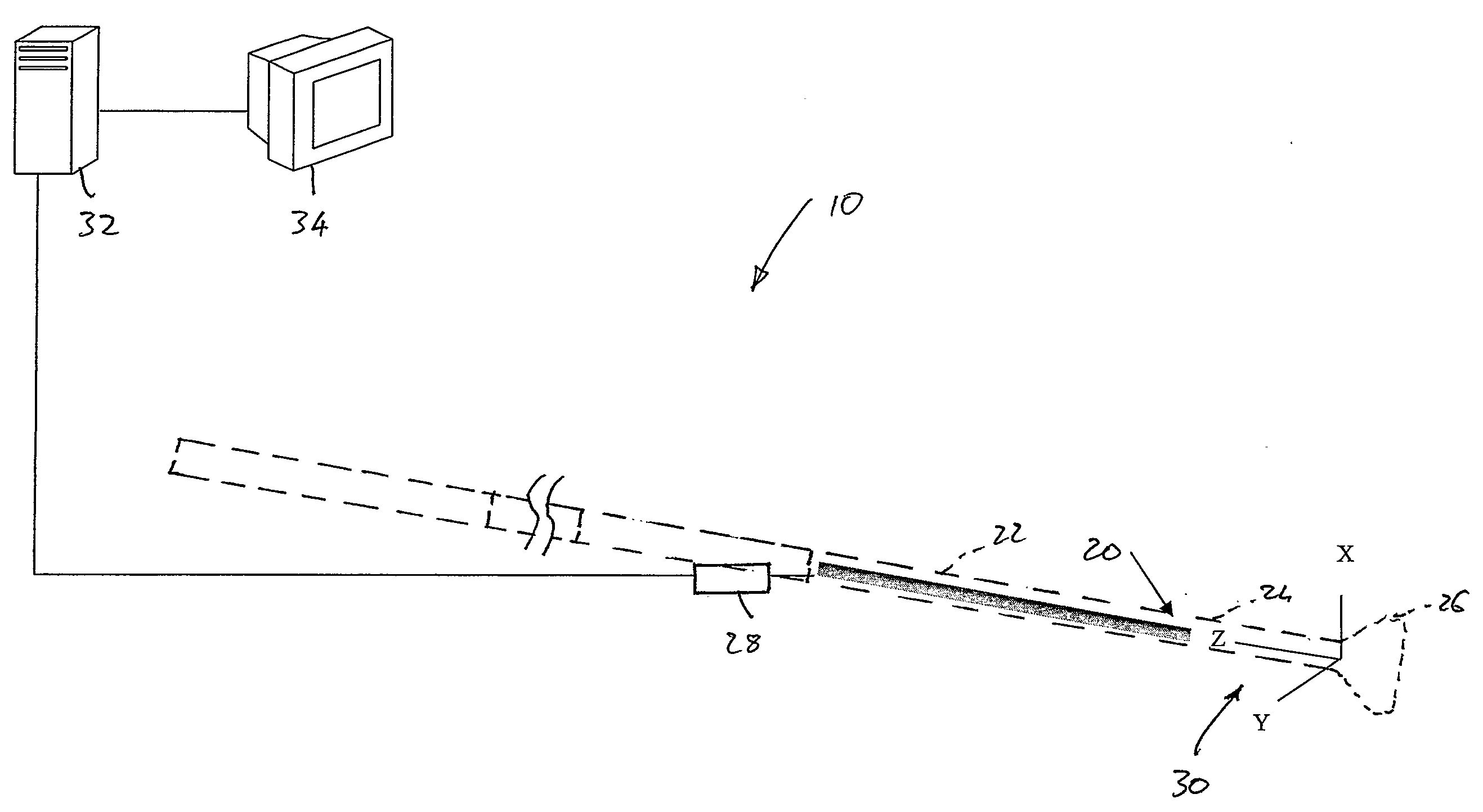
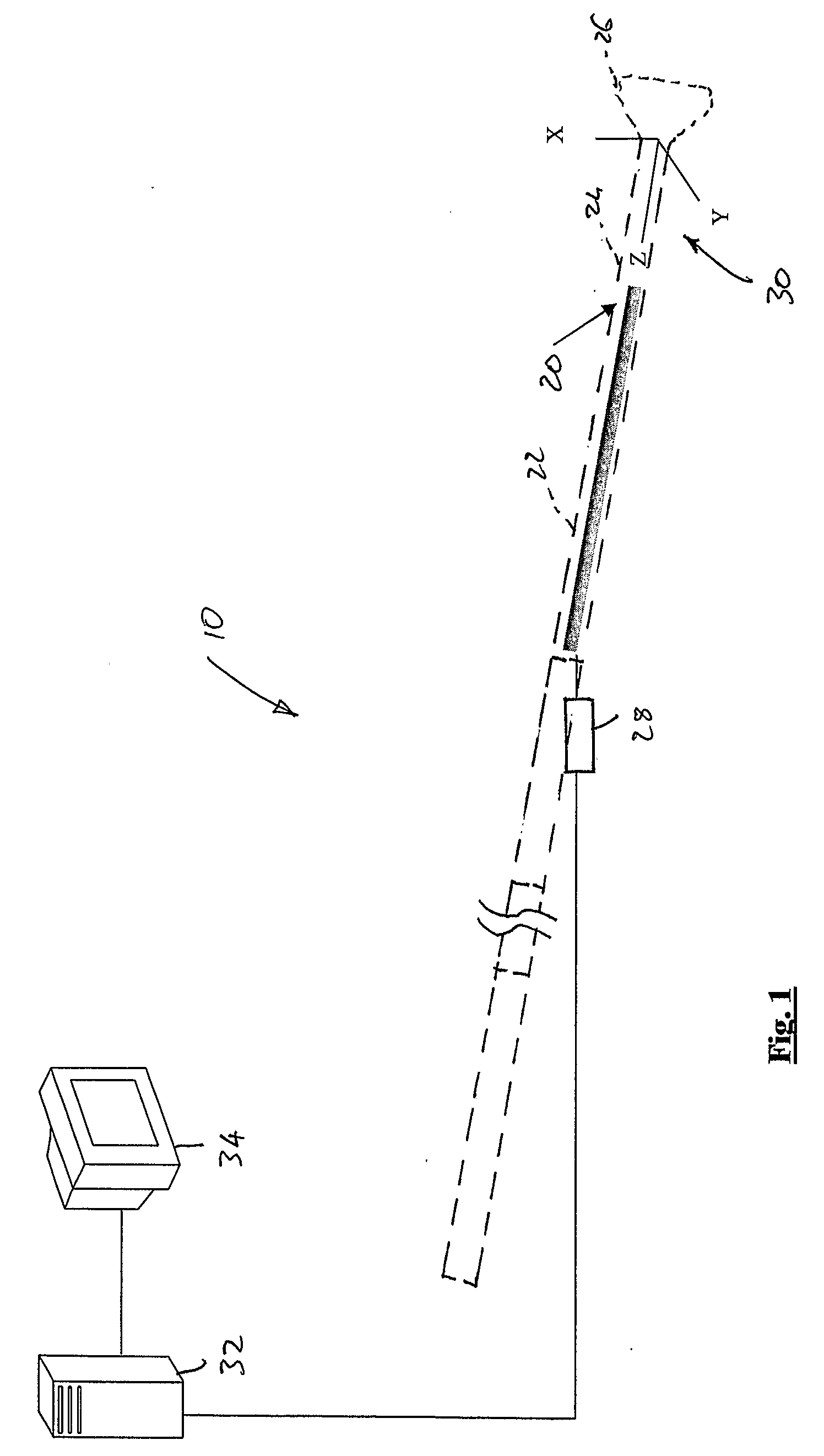
[0048]Referring initially to FIG. 1 of the drawings, an embodiment of a system for guiding a probe to a target is illustrated and is designated generally by the reference numeral 10. The system 10 can be used in numerous applications. However, for ease of explanation only, the system 10 will be described with reference to its application in the field of coal bed methane gas (CBM) extraction from a coal seam.

[0049]In such a system, a lateral hole 12 (FIG. 3) is drilled to a target in the form of a vertically extending borehole 14 to intersect the borehole 14. The lateral hole 12 is drilled through a coal seam indicated schematically at 16 in FIG. 6 of the drawings.

[0050]The system 10 incorporates a magnetic field generator or beacon 18 received in the vertical bore hole 14 to be suspended just within the coal seam 16 as illustrated in FIG. 6 of the drawings.

[0051]The system 10 further includes a survey probe 20 arranged in a drill string 22. More particularly, the survey probe 20 is ...


PUM


Abstract

A method of guiding a probe (20) to a target includes placing a magnetic field generator at the target and guiding the probe (20) to a region of the target. The probe carries a survey sensor pack (28) and the method includes using the survey sensor pack (28), firstly, to obtain a plurality of survey readings and, secondly, to obtain a plurality of magnetic beacon readings using a magnetic field generated by the magnetic field generator. A selected number of the survey readings and the magnetic beacon readings are compared and a difference between the survey readings and the magnetic beacon readings is determined. The method includes compensating for that difference thereafter to guide the probe (20) to the target.

Description

FIELD OF THE INVENTION[0001]This invention relates to guidance systems. More particularly, the invention relates to a method of, and a system for, guiding a probe to a target. The invention has particular, but not necessarily exclusive, application in the field of drilling lateral holes to a vertical borehole in the field of coal bed methane gas extraction.BACKGROUND TO THE INVENTION[0002]In a number of applications, it is necessary to guide a probe to a target through a solid medium. An example of such an application is in the field of coal bed methane gas (CBM) extraction. While the invention has been specifically developed for this application, it could be used in other applications with few, if any, modifications. The invention is therefore not limited to such an application and those skilled in the art will readily appreciate the applicability of the invention to other fields of use.[0003]In one CBM extraction method, a vertical well is drilled from the surface down through the...

Claims


Application Information

Patent Timeline
IPC IPC(8): E21B47/04G01V3/26
CPCE21B7/046E21B47/024E21B47/02216E21B47/0228
Inventor SPECK, NEIL
Owner SPECK NEIL
Why Eureka
Try Eureka