Centrifugal fluid analyzer rotor

a centrifugal fluid and analyzer technology, applied in the field of centrifugal fluid analysis rotors, can solve the problems of frequent use of complex designs which are costly and difficult to manufacture, labor intensive and time-consuming, and the limitations of previous centrifugal rotors

Active Publication Date: 2009-09-10
MICROPOINT BIOTECHNOLOGIES CO LTD
View PDF10 Cites 42 Cited by
  • Summary
  • Abstract
  • Description
  • Claims
  • Application Information

AI Technical Summary

Benefits of technology

[0010]The present inventions are directed to methods and devices that provide precise timing of accurate fluid volume flows for samples and/or reagents. The flows can take place in two o

Problems solved by technology

Such procedures are labor intensive and time-consuming.
Prior art rotors have frequently utilized complex designs which are costly and difficult to manufacture.
Previous centrifugal rotors have often been limited in the number of discrete samples and test wells they can provide.
Although these inventions teach methods of combining, mixing and/or filtering samples and reagents in a rotary device, they do not allow automatic quantitative combination of reagent and sample in the device.
The devices further do not provide precisely timed incubation of precisely combined reaction components before reaction products are transferred for detection.
U.S. Pat. No. 4,894,204 and U.S. Pat. No. 5,160,702

Method used


Image

  • Centrifugal fluid analyzer rotor
  • Centrifugal fluid analyzer rotor
  • Centrifugal fluid analyzer rotor

Examples


example 1

General Metering by Contact of Fluids

[0096]To illustrate the principles of liquid metering according to one preferred embodiment of present invention, we now refer to FIGS. 3A-F. In FIG. 3A, it shows a schematic of a microfluidic tube 2 which has a body section 3 and tip section 4. The tip section 4 has a relatively smaller diameter than the body section 3. The typical dimensions of the diameters of body section 3 and tip section 4 range from several microns to several hundred microns. The length of the tube 2 is on the order of several hundred micrometers to a few centimeters.

[0097]Referring to FIG. 3B, a first fluid 5 is added into the said microfluidic tube 2. This first fluid 5 can be, e.g., a biological fluid, an ordinary soft drink, a chemical or even drinking water. Under the capillary force, the first fluid 5 will maintain a certain amount of volume in the microfluidic tube 2 as illustrated in this schematic. At the same time, the first fluid 5 will also form a meniscus 6 at...

example 2

Multi-Assay Rotors with a Sample Metering Tubes

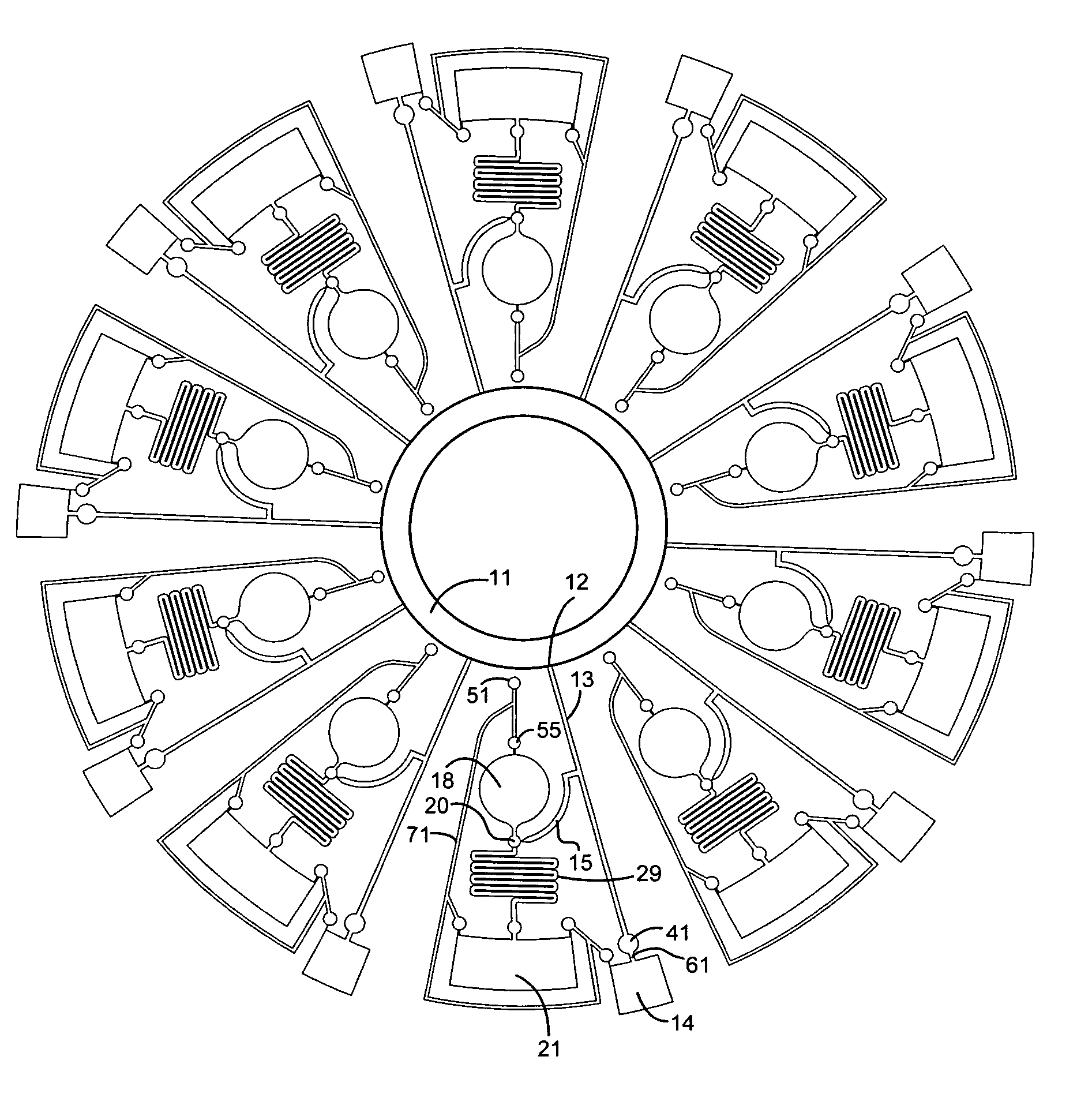
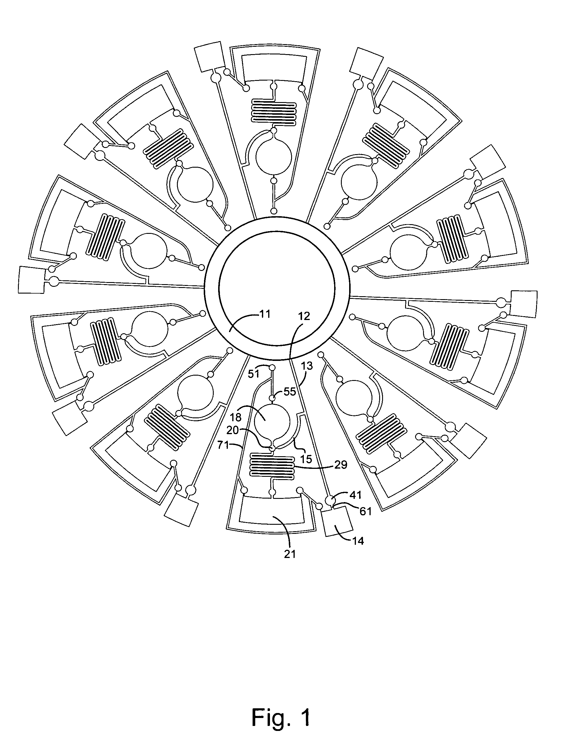
[0101]A centrifugal fluid analyzer rotor incorporating a fluid contact triggered metering tube according to one preferred embodiment of present invention is shown in FIG. 1. The rotor has a plurality of assaying units, each connected to a common sample chamber 11 through sample inlet opening 12 and sample channel 13. The sample channel 13 is connected to a liquid metering tube 15, and also waste chamber 14 through bubble 41 and a narrow section 61. Narrow section 61 and the bubble 41 form a capillary stop valve such that the sample biological fluid stored in the waste chamber 14 can not flow (e.g., by capillary action) back into the sample channel 13.

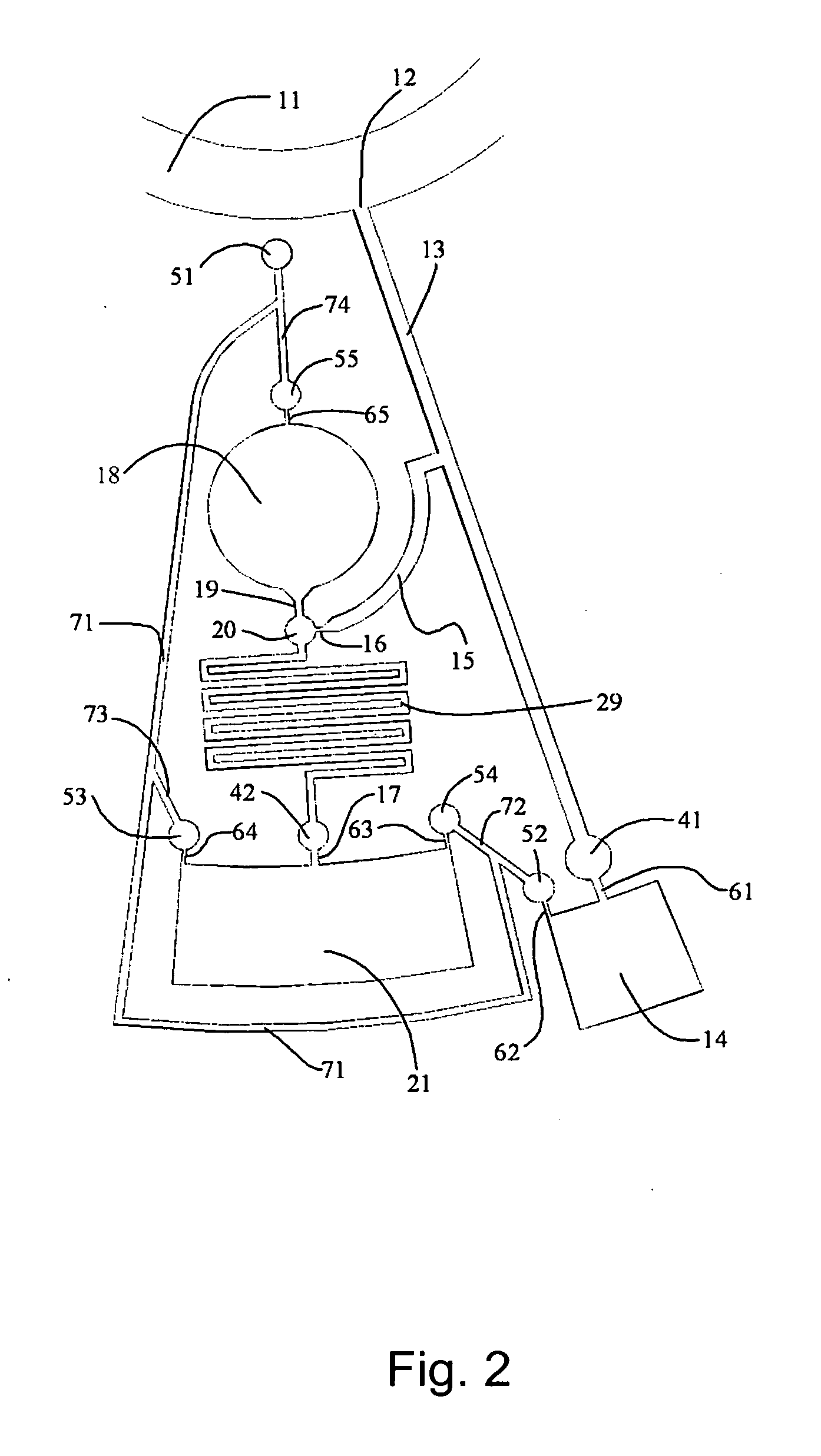
[0102]A more detailed view of one assaying unit of the centrifugal fluid analyzer rotor is shown in FIG. 2. In addition to what is described earlier, this assaying unit includes reagent chamber 18, a mixing chamber 20 and a detection chamber 21. The reagent chamber 18 is connected to the mi...

example 3

Precise Metering of a Sample Fluid into a Reagent

[0106]To understand more about the working principles of the centrifugal fluid analyzing rotor according to one preferred embodiment of present invention, we refer to FIGS. 4A-H. These figures schematics that are used to illustrate the principles, but are not intended to limit the scope of the inventions. In FIG. 4A, sample chamber 11, reagent chamber 18, liquid metering tube 15, waste chamber 14, and detection chamber 21 are all fluidly connected through a network of micro channels, e.g., similar to those shown in FIGS. 1 and 2. In reagent chamber 18, reagent 22 is pre-packaged in a known desired volume, as shown in FIG. 1. To simplify the drawings, the mixing maze 29 and bubble 42 are not drawn in the figure. In this figure, the (vertical) axis of rotation 1 is shown such that the rotation of the assay analyzing unit is in the plane as shown. In this case, FIGS. 4A to 4H show the plan view of an assay analyzing unit. The sample cham...


PUM

PropertyMeasurementUnit
Angular velocityaaaaaaaaaa
Speedaaaaaaaaaa

Abstract

This invention provides rotors and methods of precisely metering a sample fluid and mixing the sample with a reagent. The rotors have a metering tube of defined volume that fills until sample flow is stopped by surface tension of a meniscus at a capillarity port, while excess sample is stripped from the metering tube inlet by centripetal force of the spinning rotor. By spinning the rotor at a higher speed, a reagent can be forced from a reagent chamber to contact the meniscus, breaking the surface tension and allowing the metered sample to mix with the reagent.

Description

CROSS-REFERENCE TO RELATED APPLICATIONS[0001]This application claims priority to and benefit of a prior U.S. Provisional Application No. 61 / 063,670, Centrifugal Fluid Analyzer Rotor, by Mark Wang, et al., filed Feb. 4, 2008. The full disclosure of the prior application is incorporated herein by reference.FIELD OF THE INVENTION[0002]The invention is directed to centrifugal fluid analysis rotors and methods that automatically proportion and mix two or more fluids in an analytical technique. Devices include a sample metering tube that holds a sample fluid at a capillary port to a mixing chamber, and reagent held at a capillary port at the mixing chamber. Spinning the rotor forces reagent into the chamber to contact the meniscus of the sample, causing the sample to flow and mix with the reagent in precise proportions in the chamber. Methods include rotating a rotor of the invention at a first rotational speed to precisely fill the sample fluid metering tube without spilling past the sam...

Claims


Application Information

Patent Timeline
IPC IPC(8): G01N1/10
CPCG01N35/00069Y10T436/2575G01N2035/00495G01N2035/00257
Inventor WANG, MARKZHANG, NAN
Owner MICROPOINT BIOTECHNOLOGIES CO LTD
Why Eureka
Try Eureka