Electrical Connector Assembly and Method for Using the Same

a technology of electrical connectors and connector assemblies, which is applied in the direction of electrical discharge lamps, contact members penetrating/cutting insulation/cable strands, coupling device connections, etc., can solve the problems of not disclose the adaptable termination apparatus of the profiri patent, add significant time and labor to the assembly process,

Active Publication Date: 2009-09-10
AMPHENOL CORP
View PDF12 Cites 6 Cited by
  • Summary
  • Abstract
  • Description
  • Claims
  • Application Information

AI Technical Summary

Benefits of technology

[0007]It is a further object of the present invention to provide a multi-circuit electrical connector that rigidly secures the shield layer of a wire assembly without risk of a disconnection. It is desired for such connector to also include two or more conductive portions in connect with the shield layer to ensure conductivity and / or grounding.

Problems solved by technology

This step adds significant time and labor to the assembly process.
The Profiri patent also does not disclose a termination apparatus adaptable for use with a wire assembly having an internal shield layer or an insulation layer.

Method used


Image

  • Electrical Connector Assembly and Method for Using the Same
  • Electrical Connector Assembly and Method for Using the Same
  • Electrical Connector Assembly and Method for Using the Same

Examples


Embodiment Construction

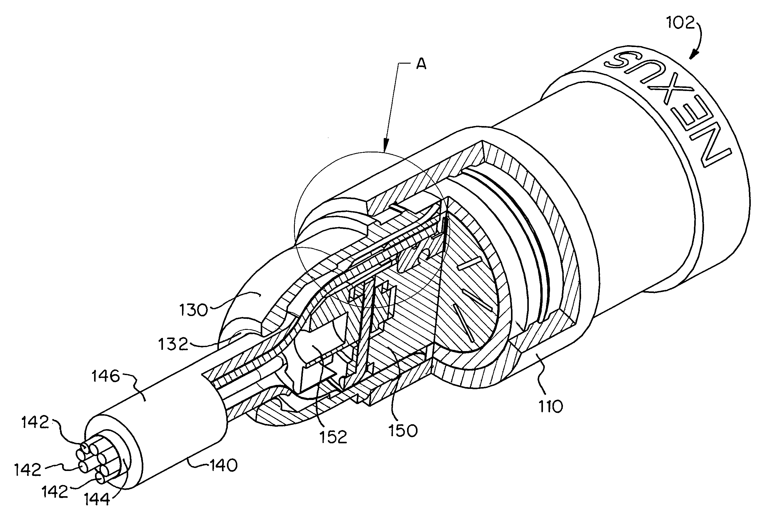
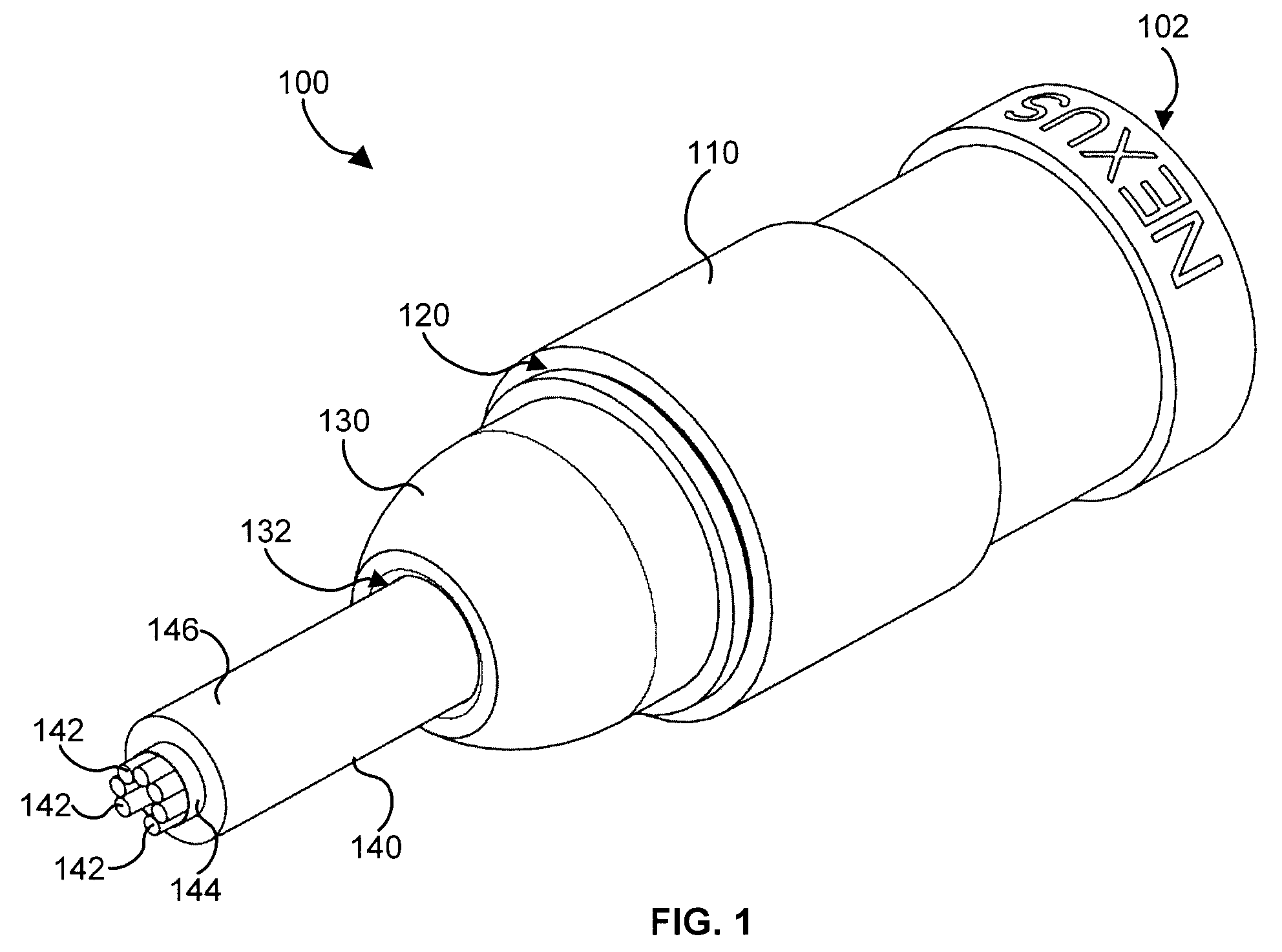
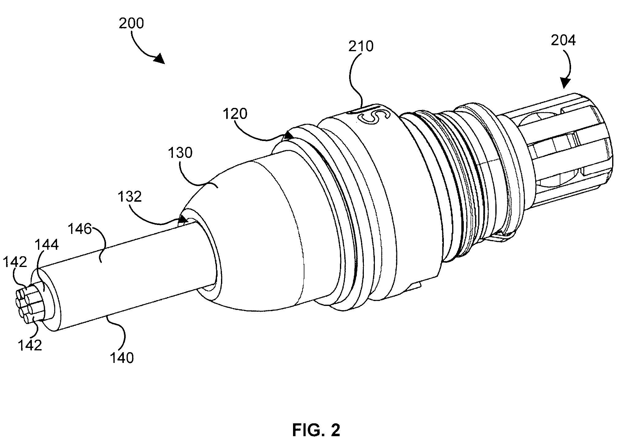
[0024]FIG. 1 shows an electrical connector 100 according to an exemplary embodiment of the present invention. The connector 100 includes a female connection jack 102. FIG. 2 shows another electrical connector 200. The connector 200 includes a male connection plug 204. The connector 200 and connector 100 are adapted for self aligned snap engagement with each other.

[0025]As shown in FIGS. 1 and 2, the connector 100 / 200 includes a housing 110 / 210 with an opening 120. The connector 100 / 200 further includes a shell or cover 130. The shell 130 includes a hole or aperture 132 for receiving a wire assembly 140. The shell 130 is adapted for slideable engagement with the housing 110 / 210. In preferred embodiments, each of the shell 150 and the housing 110 / 210 are comprised of a conductive material. For example, the shell 150 and housing 110 / 210 may comprise aluminum.

[0026]FIGS. 3A-6B show cutaway and detailed views of the connector 100 / 200 according to an exemplary embodiment of the present in...


PUM


Abstract

An electrical connector including a housing including an opening, a carrier assembly for receiving one or more leads from a wire assembly and extending via the opening, an annular gap between an inside surface of the opening and the carrier assembly, a shell including a hole for receiving the wire assembly, the shell adapted for slideable engagement with the housing in the annular gap, and wherein the slideable engagement between the shell and the housing severs a distal portion of a shield layer of the wire assembly and secures a proximal portion of the shield layer in the annular gap.

Description

FIELD OF THE INVENTION[0001]The invention relates to an electrical connector assembly, and more specifically to a multi-circuit electrical connector assembly for connecting shielded wire assemblies.BACKGROUND OF THE INVENTION[0002]Many different electrical connectors and multi-circuit electrical connectors are known. For example, commonly owned U.S. Pat. No. 3,907,395 to Flanagan discloses a multi-circuit electrical connector with an advantageous means for self-effectuating connection of the circuits. The connector disclosed in the Flanagan patent is adaptable for use with shielded wires. However, as with many other connectors, the shield layer of the wire must be measured and cut to length by hand before completing the assembly. This step adds significant time and labor to the assembly process.[0003]U.S. Pat. No. 6,137,056 to Miyazaki discloses a construction for connecting a shield layer of a shielded cable. The construction includes an inner tubular member that is inserted inside...

Claims


Application Information

Patent Timeline
Patent Type & Authority Applications(United States)
IPC IPC(8): H01R24/00
CPCH01R4/28H01R13/506H01R9/032H01R13/65912
Inventor FARAHANI, FEREIDOUN A.FLANAGAN, WILLIAM H.
Owner AMPHENOL CORP
Why Eureka
Try Eureka