
Method for establishing radiofrequency links via a multispot satellite

Inactive Publication Date: 2009-09-10
EUTELSAT
View PDF13 Cites 7 Cited by
  • Summary
  • Abstract
  • Description
  • Claims
  • Application Information

AI Technical Summary

Benefits of technology

[0041]It is an object of the present invention to provide a method for establishing radiofrequency links via a multiport satellite between at least one terrestrial station and a service area composed of a plurality of cells, said method allowing the coverage to be improved in the case of the loss of one or a plurality of spots.

Problems solved by technology

In fact, the least failure involving the loss of spots has a direct impact on the cells associated with these spots, the coverage of which is no longer guaranteed.
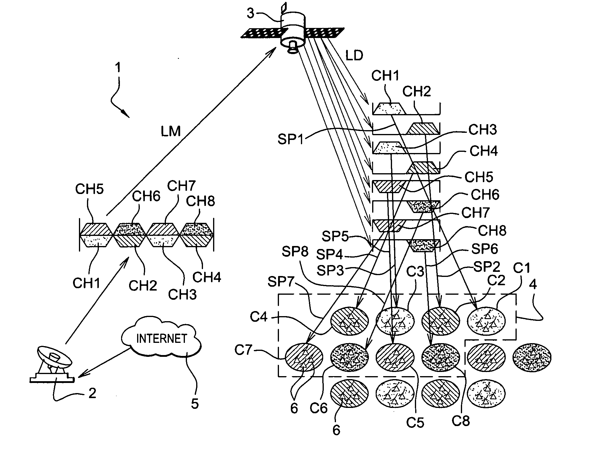
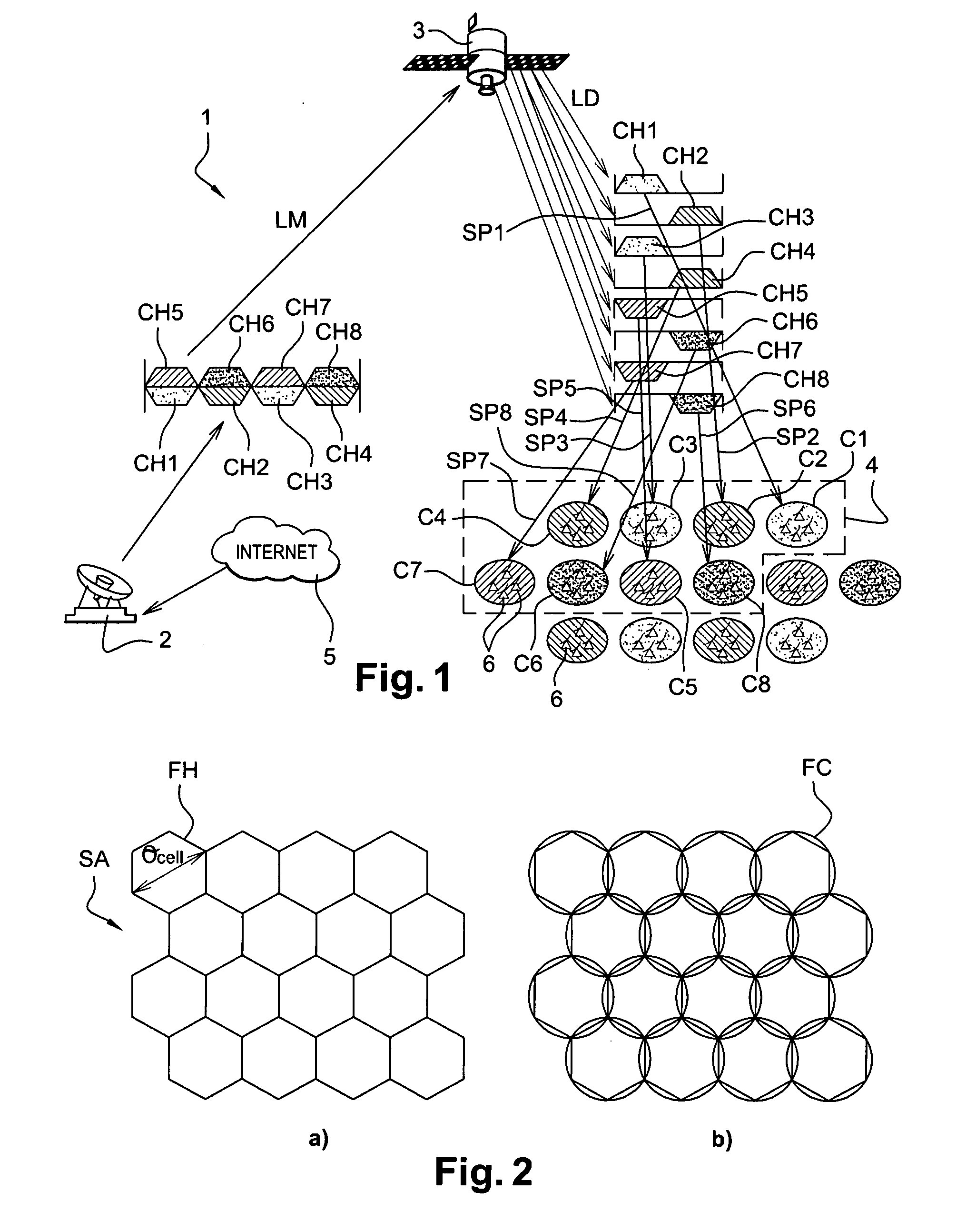
Such a failure may be due for example to:the failure of a terrestrial station implicating the loss of all of the spots generated from the station (in our above example 16 spots);the breakdown of an antenna on board the satellite (therefore generally 25% of the spots are lost originating from the satellite with four antennae on the satellite and hence 25% of the area covered by the satellite);the poor functioning of a multiplexer or a filter which will involve the loss of the spots directly in correspondence;the failure of a high power amplifier HPA generally formed by a channel amplifier CAMP and a travelling wave tube amplifier TWTA, or the partial failure of the power system on the satellite: the loss can be from one to several spots; thus, a spot will be lost if this spot is generated by a single amplifier and this amplifier (and its redundant amplifier) is lost; two spots (or more generally N spots) will be lost if the amplifier (and its redundancy) is used by two (more generally N) spots (i.e. two spots per tube or more generally N spots per tube); even four spots can be lost if the loss of the supply system is concerned, taken in common by two amplifiers (electronic power conditioner double), which are themselves used to generate two spots each.

Method used


Image

  • Method for establishing radiofrequency links via a multispot satellite
  • Method for establishing radiofrequency links via a multispot satellite
  • Method for establishing radiofrequency links via a multispot satellite

Examples


Embodiment Construction

[0071]In all the figures, the common elements bear the same reference numbers.

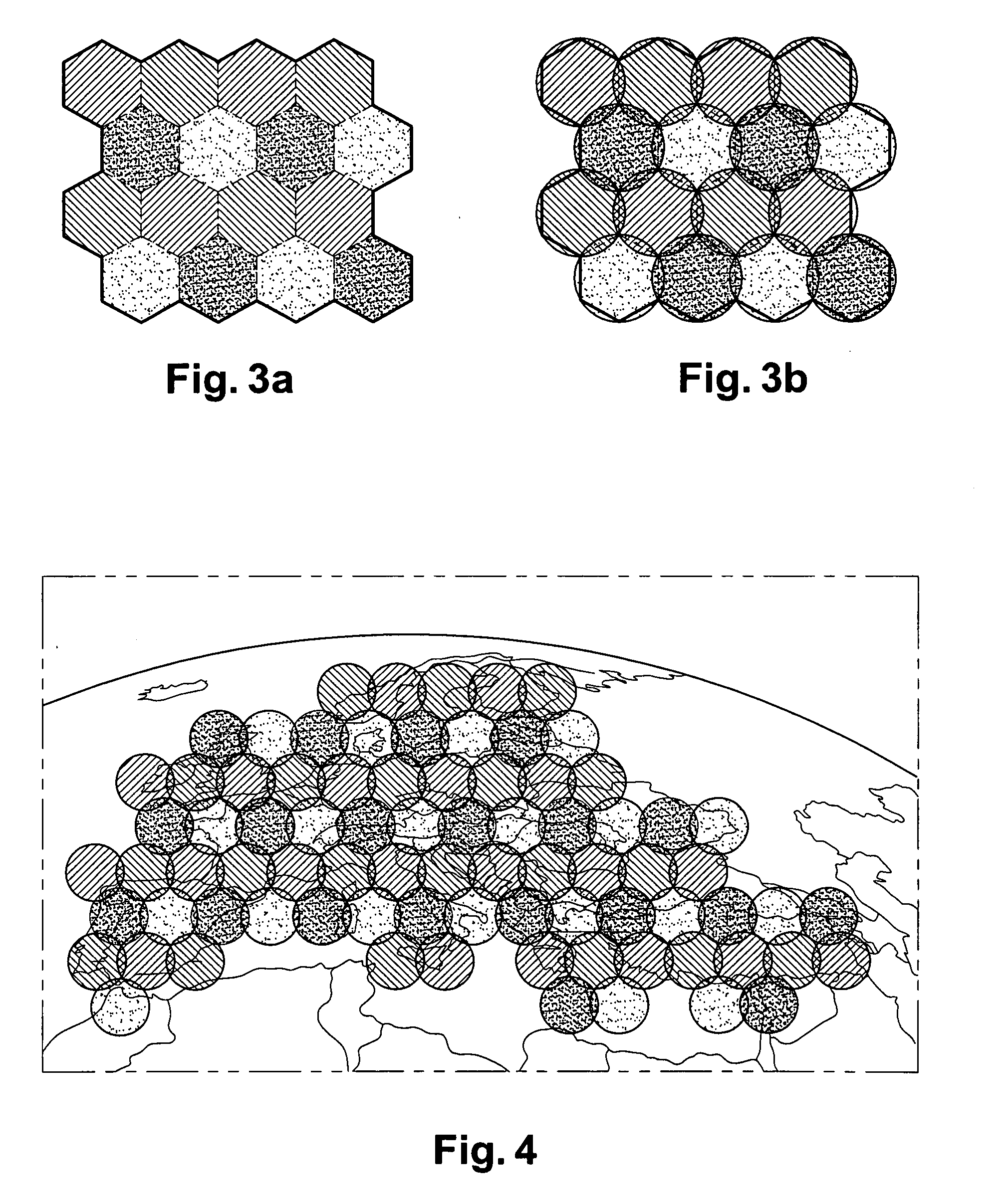
[0072]FIG. 6 takes up again the illustration of FIG. 3b) in the case of loss of the yellow spots. Such a situation may occur for example in the case of failure of the reflector of the antenna of the satellite in charge of the generation of the yellow spots. This type of breakdown involves the loss of a quarter of the spots. As we have already mentioned above, the lost cells CPJ associated with the yellow spots are each surrounded by six contiguous cells, none of which is a cell associated with a yellow spot (two cells associated with a green spot, two cells associated with a blue spot and two cells associated with a red spot).

[0073]The method according to the invention allows the loss of coverage engendered by these lost cells to be reduced.

[0074]A first form of embodiment of the method according to the invention is illustrated in FIGS. 9a) and 9b). As we have already mentioned above, an antenna spot assoc...


PUM


Abstract

A method for establishing radiofrequency links via a telecommunication satellite having several spots, designated a multispot satellite, between at least one terrestrial station and a service area composed of a plurality of elementary covering zones, designated cells, each cell comprising a plurality of terrestrial terminals is disclosed. This type of satellite allows the use of several spots of antennae on board the satellite to cover contiguous geographical zones or cells, instead of a single broad spot. Each cell is associated with a spot to which a frequency band is attributed. In the case of the loss of a spot associated with a cell, designated a faulty cell, the spot (FR1, FR2, FB1, FB2, FV1, FV2) associated with at least one contiguous cell (CR1, CR2, CB1, CB2, CV1, CV2) to the said faulty cell is likewise associated with a part of the said faulty cell so that the area (CPJ′) of said faulty cell is reduced.

Description

[0001]This claims priority to French Patent Application FR 08 / 51432, filed Mar. 5, 2008, the entire disclosure of which is incorporated by reference herein.BACKGROUND[0002]The present invention concerns a method for establishing radiofrequency links via a telecommunication satellite having several spots, designated multispot satellite, between at least one terrestrial station (designated as gateway) and a service area composed of a plurality of elementary covering zones, designated as cells, each cell comprising a plurality of terrestrial terminals. This type of satellite allows the use of several antenna spots on board the satellite to cover contiguous geographical zones or cells, instead of a single broad spot.[0003]Such multispot satellites allow several radiofrequency links to be established occupying the same frequency band on different spots.[0004]In the case of a broadband satellite telecommunication system, the satellite is used in a bidirectional manner, i.e. at the same ti...

Claims


Application Information

Patent Timeline
IPC IPC(8): H04Q7/36
CPCH01Q3/26H04B7/2041H01Q25/00H01Q3/30
Inventor FENECH, HECTORLANCE, EMMANUELDUTRONC, JACQUES
Owner EUTELSAT
Learn More