Rod Locking Instrument

Inactive Publication Date: 2009-09-10
PIONEER SURGICAL TECH INC
View PDF69 Cites 113 Cited by
  • Summary
  • Abstract
  • Description
  • Claims
  • Application Information

AI Technical Summary

Benefits of technology

[0012]The instrument may also comprise one or more structures for shifting the grasping device from an open position to a clamped position. For instance, the grasping device may include a slit or other gap having a wide portion and a narrow portion, so that a moveable structure that travels through the gap, such as a deflection member extending transversely through the gap, deflects clamping portions of the grasping device and widens the gap when the deflection member is disposed in the narrow portion of the passage and allows the clamping portions to shift toward one another when the deflection member is disposed in the wide portion of the gap. Alternatively, an outer sleeve may be provided to translate along the exterior of the grasping device, forcing clamping portions of the grasping device toward one another during travel of the sleeve.
[0014]A reducing member may also be provided to assist in shifting the spinal rod into seated engagement within the coupling assembly. The reducing member may, for instance, exert a shifting force upon the rod at spaced locations along the rod axis on either side of the area contacted by the drive rod, providing greater rod stability during operation of the instrument. Such a configuration also allows the rod to be reduced prior to introduction of the cap and held in place while the cap is secured to the coupling assembly without interfering with locking of the cap to the coupling assembly and without requiring the reducing member to be moved out of the way prior to locking of the cap. In one form, shifting of the reducing member may be coupled to shifting of the drive member so that a single actuator shifts the reducing member and the drive member.
[0015]If the drive member, grasping device, and reducing member are all coupled together, a single actuator may be effective for causing clamping of the grasping device, shifting of the reducing member, and / or shifting of the drive rod at various orientations of the actuator or upon activating the actuator a predetermined number of times.

Problems solved by technology

Some pedicle screw systems lack features that enhance and / or benefit newer, minimally invasive surgery (MIS) techniques that are more commonly being used for spinal surgeries.
For instance, installation and locking of coupling assemblies often involves complex manipulation of a plurality of components of the screw system, and sometimes also requires a screw or other anchor to be assembled with a rod-receiving device prior to implantation.
The assembly may obstruct the working space, making it more difficult to insert the anchor into a vertebra and manipulate the coupling device during surgery.
Furthermore, assemblies with polyaxial fixation devices in the prior art ordinarily rely on downward force of the rod against the head of the bone anchor to secure the bone anchor against pivoting, so that the assembly, and specifically the rod receiving portion thereof, is provided with little support or stability prior to full locking of the rod.
Some pedicle screw systems also include rather large and bulky assemblies to secure a rod, thus increasing opportunities for tissue damage in and around the surgical site during installation.
Many of these systems also include set-screw type locking mechanisms or multi-part cap structures that require rotation or complex manipulation of small components and / or require a significant portion of the assembly to be located above the rod, increasing the height (profile) of the implants extending radially away from the spinal column, which may cause patient discomfort after implantation.
Systems with set screws for securing the rod within the coupling assembly also lack a predetermined locking position, requiring a surgeon to turn the set screw a number of revolutions in order to secure the rod.
When locking the rod in place with a set screw or other similar structure, the surgeon must also determine when the assembly“feels” locked, often resulting in overtorquing of the locking mechanism or false locking of the assembly.
Cross-threading is also often a problem in such systems, and can result in damage to the assembly or a failure to fully lock the cap.
Furthermore, the actuators in those systems often rely on threaded drive members to cause shifting of components, so that a member must be rotated a great number of revolutions in order to effect any significant amount of linear shifting.
Some such systems also have deficiencies such as an inability to fully stabilize the rod during linear shifting, failure to provide indication of when full locking of the cap and rod-receiving device has been achieved, and failure to provide mechanisms to allow multiple predetermined stages of locking for the assembly (i.e. a first “provisional” locking stage that prevents the rod from escaping the rod-receiving device but allows for rod adjustment, followed by a “full” locking stage that immobilizes the rod with respect to the coupling device).
Furthermore, many of these systems are designed specifically for use with set screws or rotating cap members, and therefore may not be compatible with other types of coupling assemblies.

Method used


Image

  • Rod Locking Instrument
  • Rod Locking Instrument
  • Rod Locking Instrument

Examples


Embodiment Construction

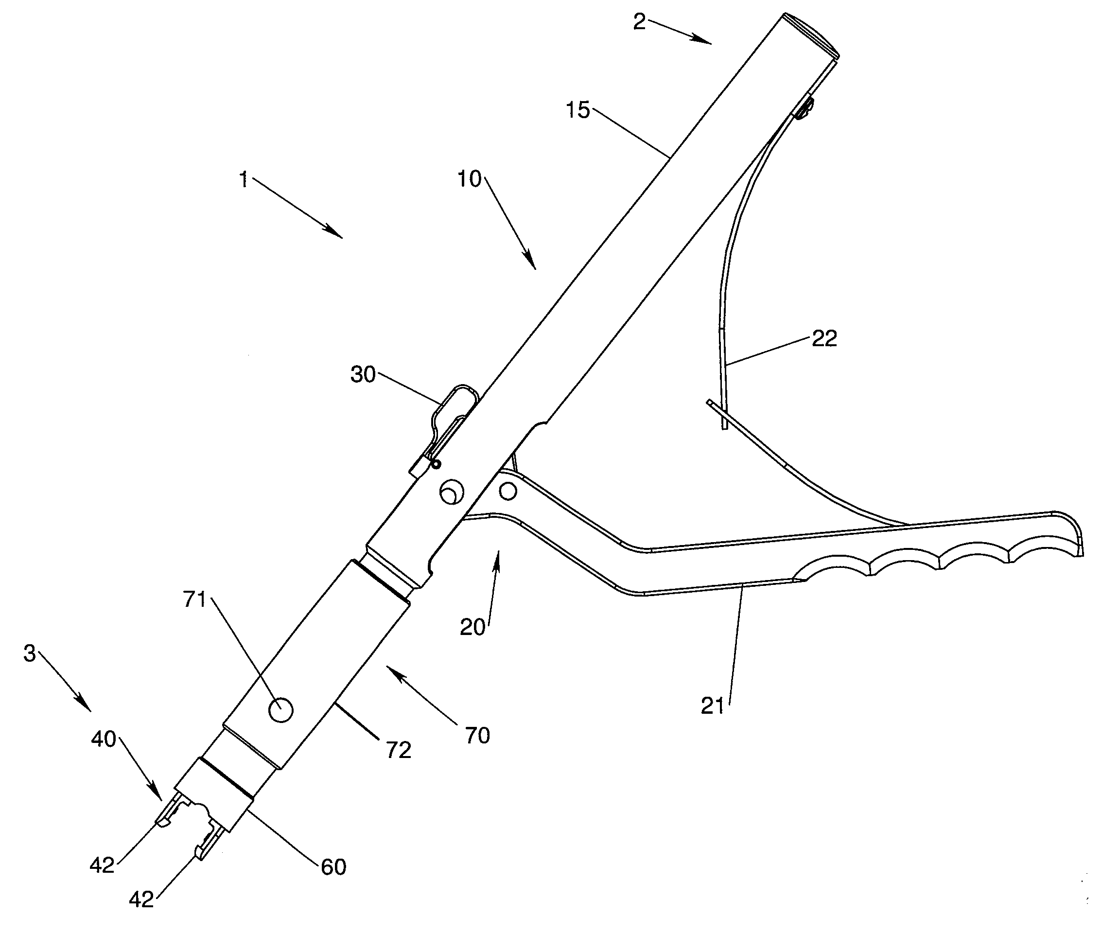
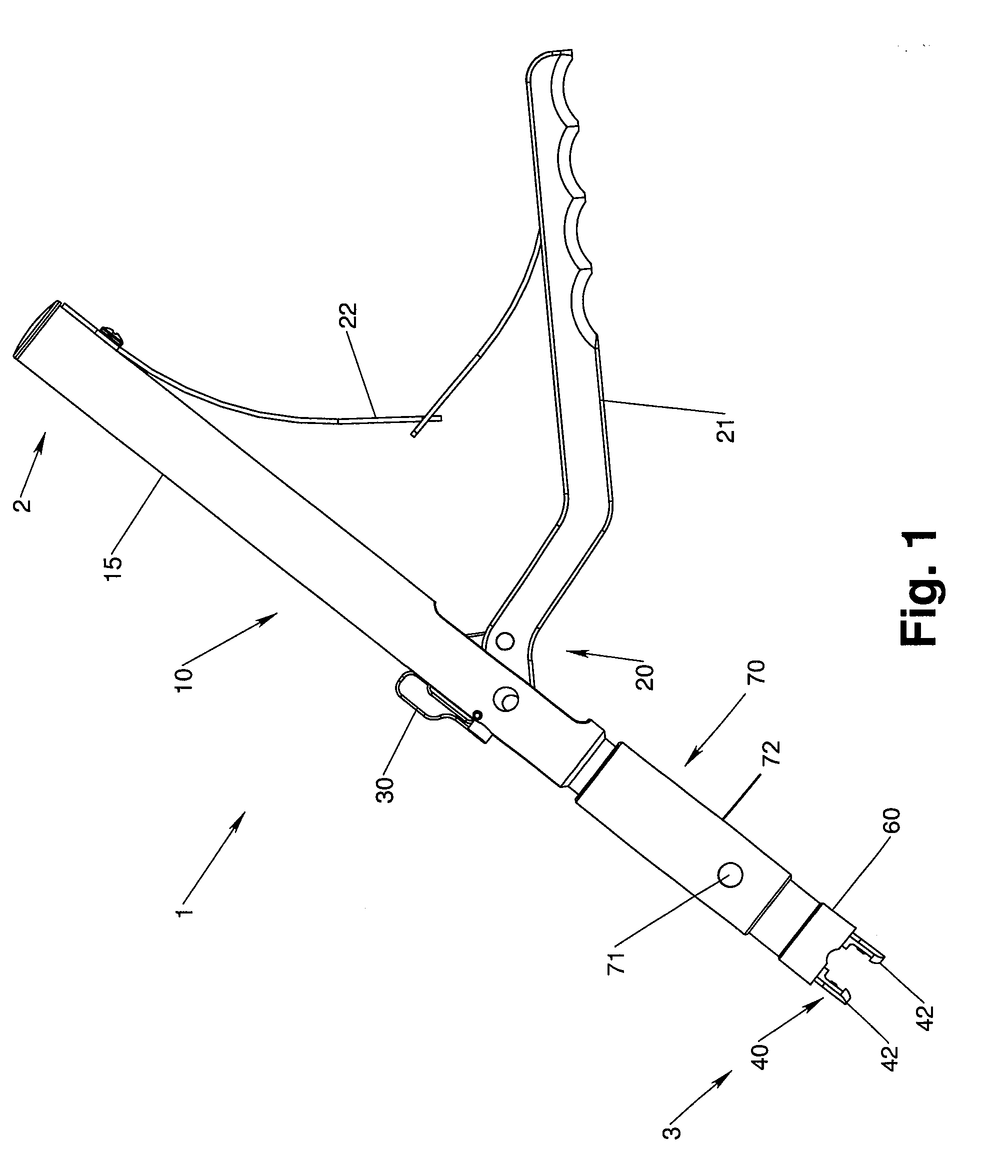
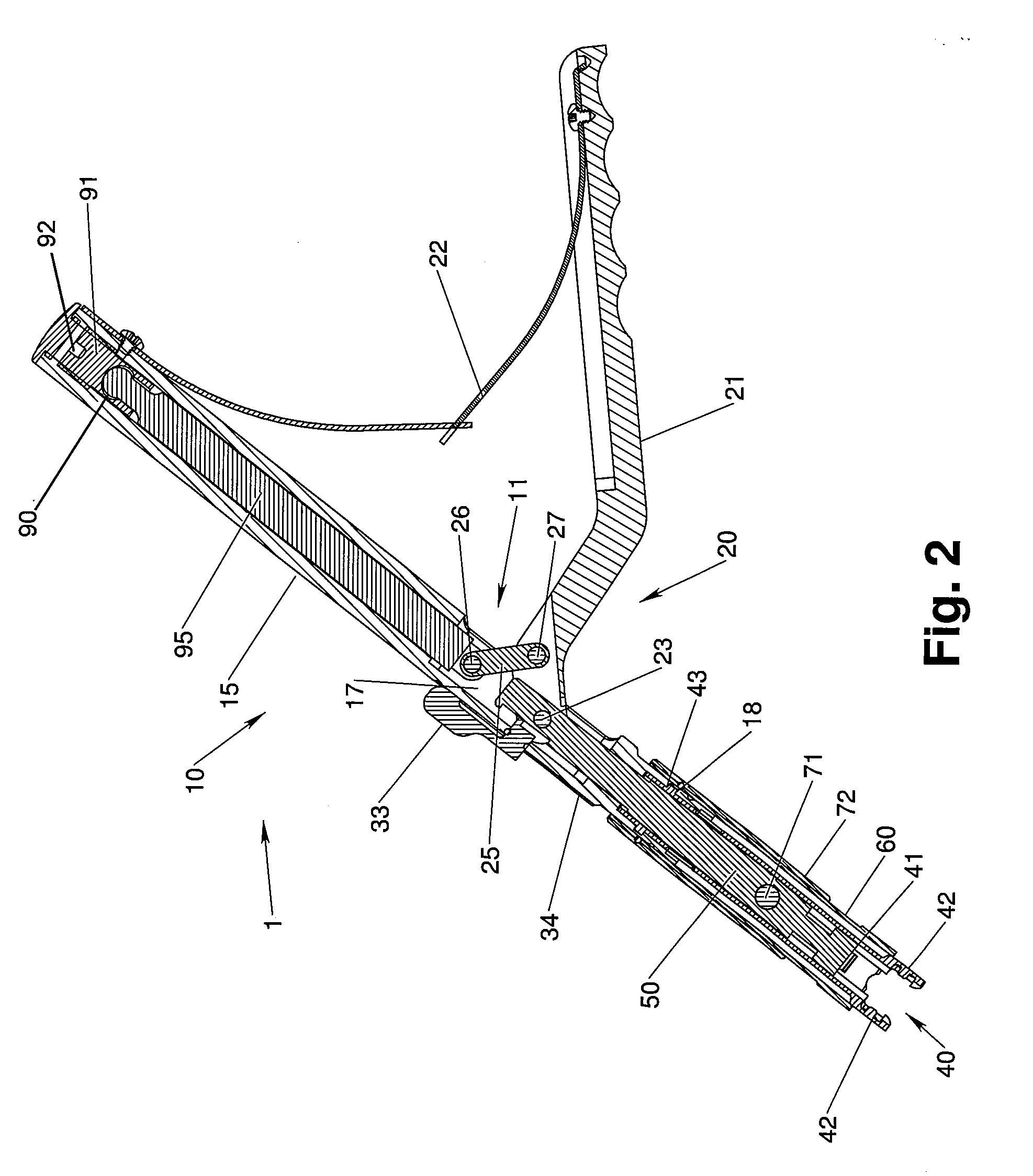
[0057]One exemplary instrument for securing a rod and an anchor member within a coupling assembly is shown in FIGS. 1 and 2. The illustrated embodiment comprises an instrument body 10 having a handle 15, an actuator assembly 20 having an actuator in the form of a lever 21, a radially expandable grasping device 40 extending axially from the instrument body, an axially shiftable drive member 50 extending from the instrument body and disposed within the grasping device, a reducing member in the form of a reducing sleeve 60 surrounding the grasping device and axially moveable with respect thereto, and a drive coupler 70 having a coupling sleeve 72 and a coupling pin 71. The coupling of the drive member 50 to the reducing member 60 and drive coupler subassembly 70 is illustrated by the side cross-sectional view of FIG. 3. The components of the instrument 1 are shown disassembled in FIG. 4 for reference in the following discussion.

[0058]An exemplary coupling assembly of the type that may ...


PUM


Abstract

Instruments and methods are provided for securing a spinal rod in one or more coupling devices secured to the spine by one or more anchor members. The instruments include members for grasping the coupling device and members for shifting one or more elements along a linear path to fix the position of an anchor member and / or fix the position of the rod with respect to the vertebra.

Description

CROSS REFERENCE TO RELATED APPLICATIONS[0001]This application claims the benefit of U.S. provisional patent applications 61 / 024,465, filed Jan. 29, 2008, and 61 / 024,470, filed Jan. 29, 2008, both of which are hereby incorporated fully by reference as if set forth herein.FIELD OF THE INVENTION[0002]The present systems and methods relate to instruments for manipulating bone fixation devices. More particularly, the present systems and methods provide for instruments for locking components of a coupling device configured to facilitate the fixation of vertebral bodies, such as a low profile screw assembly.BACKGROUND OF THE INVENTION[0003]Various devices for internal fixation of bone segments in the human or animal body are known in the art. One type of system is a pedicle screw system, which is sometimes used as an adjunct to spinal fusion surgery, and which provides a means of anchoring an implantable member to a spinal segment. A conventional pedicle screw system comprises a pedicle sc...

Claims


Application Information

Patent Timeline
IPC IPC(8): A61F5/00
CPCA61B17/7032A61B17/7086A61B17/7037
Inventor HOFFMAN, JEFFREYMOHAR, JOSEPHNORMAN, MARIA M.BERREVOETS, GREGORY
Owner PIONEER SURGICAL TECH INC
Why Eureka
Try Eureka