Method For Calculating Rotation Center Point And Axis Of Rotation, Method For Generating Program, Method For Moving Manipulator And Positioning Device, And Robotic System
- Summary
- Abstract
- Description
- Claims
- Application Information
AI Technical Summary
Benefits of technology
Problems solved by technology
Method used
Image

Examples
first embodiment
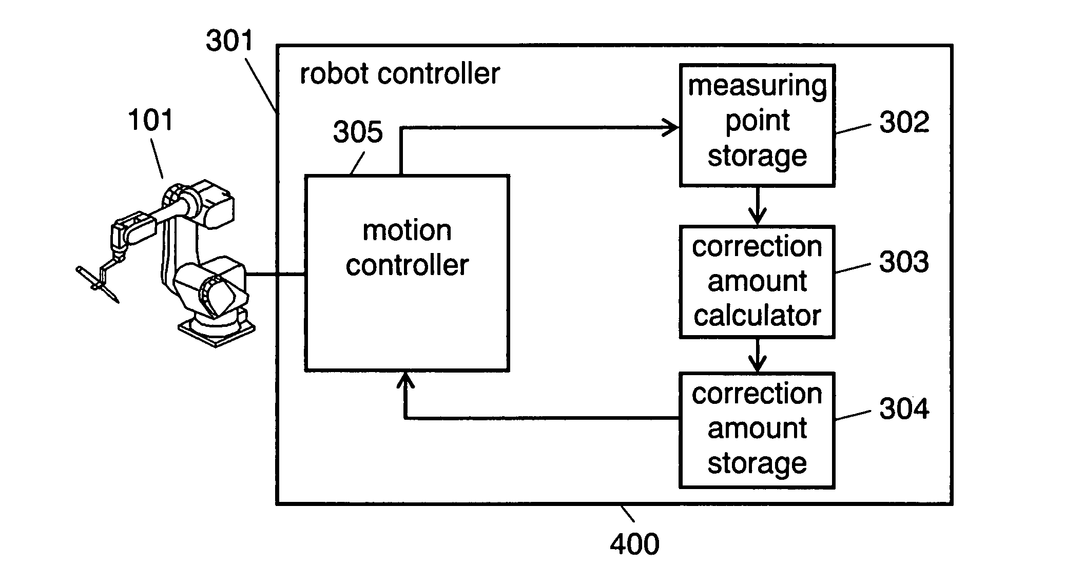
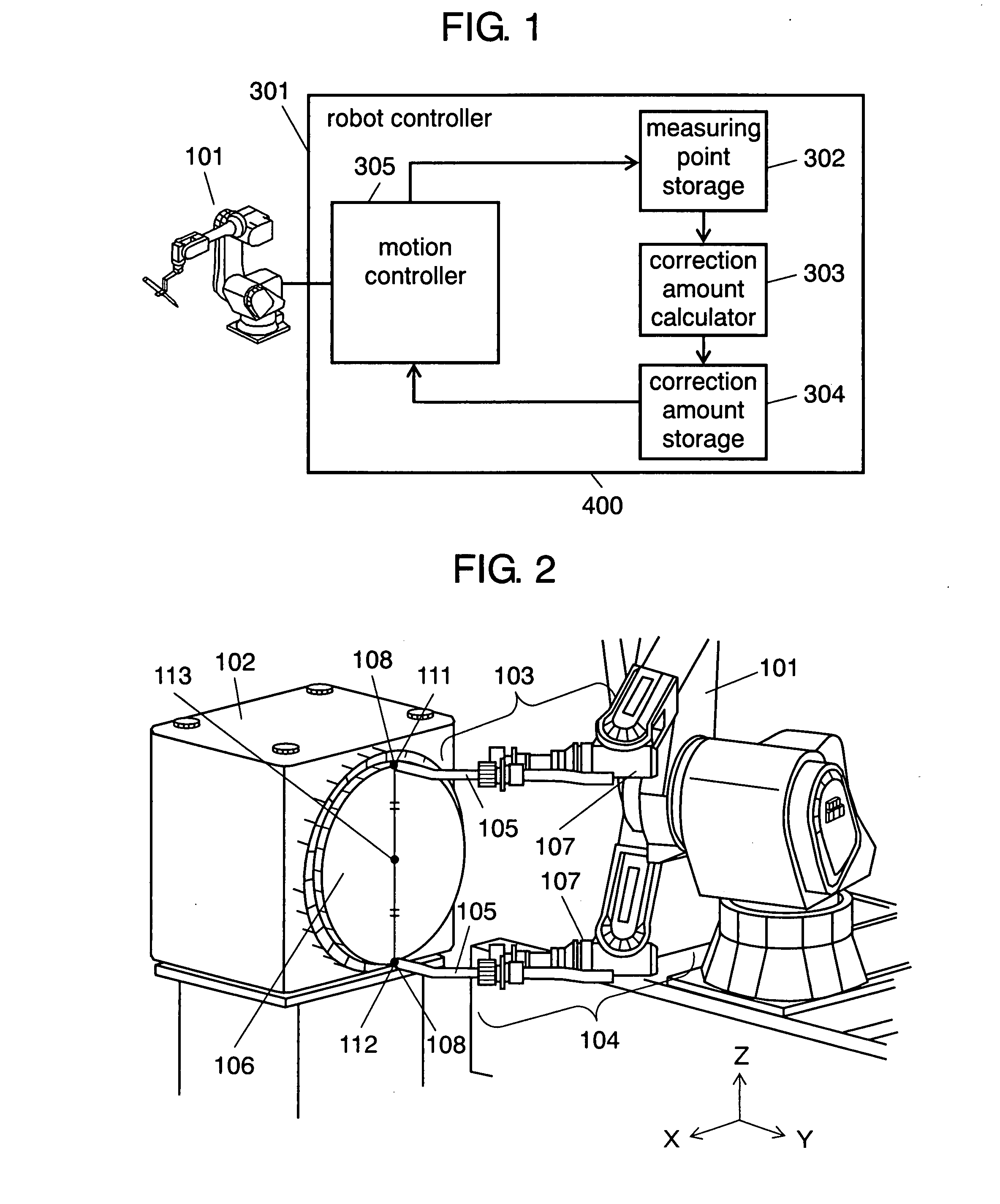
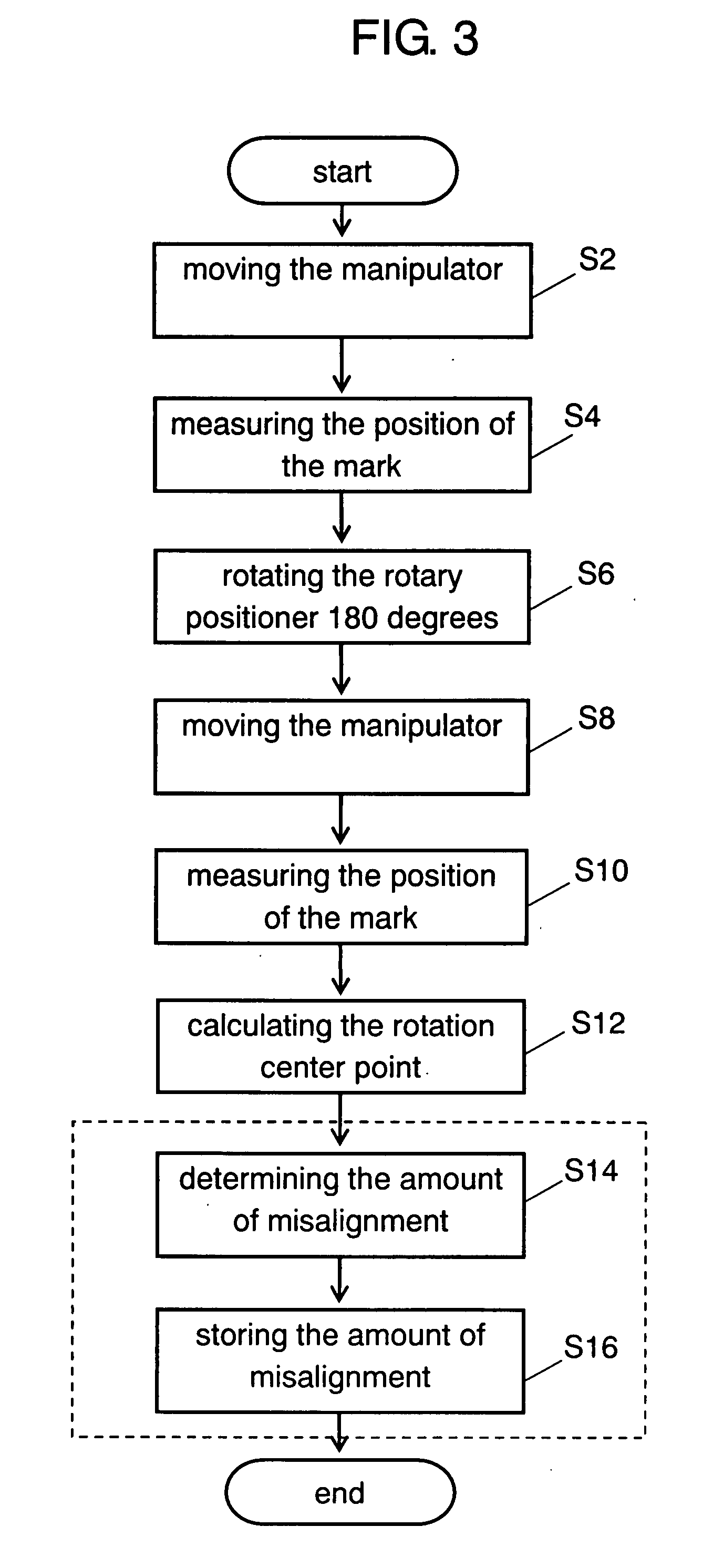
[0065]A first embodiment of the present invention is described as follows with reference to FIGS. 1 and 2. FIG. 1 shows a structure of robotic system 400 according to the first embodiment. FIG. 2 is a schematic diagram showing a method for calculating the rotation center point of the plane of rotation of a rotary positioner, which is an example of a positioning device according to the first embodiment.
[0066]As shown in FIG. 1, robotic system 400 includes manipulator 101 and robot controller 301, which controls manipulator 101.
[0067]Robot controller 301 includes measuring point storage 302, correction amount calculator 303, correction amount storage 304, and motion controller 305. Measuring point storage 302 stores the location information of a measuring point measured by moving manipulator 101. Correction amount calculator 303 calculates the amount of correction of an operating program based on the location information stored in measuring point storage 302. Correction amount storage...
second embodiment
[0087]A second embodiment of the present invention is described as follows with reference to FIGS. 1 and 4. FIG. 4 is a schematic diagram showing a method for calculating an axis of rotation connecting the rotation center points of two opposite planes of rotation according to the second embodiment.
[0088]In the present embodiment, the same components as those in the first embodiment will be referred to with the same numerals as those in the first embodiment and not described in detail again. Similar to robotic system 400 of the first embodiment, robotic system 402 includes robot controller 301 which controls manipulator 101.
[0089]Robotic system 402 of the present embodiment can calculate rotation center points 113 and 216 of two opposite planes of rotation 106 and 203 which hold a workpiece together. Robotic system 402 can also calculate axis of rotation 217 connecting rotation center points 113 and 216.
[0090]In FIG. 4, manipulator 101 is used to measure the rotation center point of ...
third embodiment
[0116]A third embodiment of the present invention is described as follows with reference to FIG. 6. FIG. 6 shows the structure of robotic system 404 according to the third embodiment. In the present embodiment, the same components as those in the first and second embodiments will be referred to with the same numerals as those in the first and second embodiments and not described in detail again.
[0117]Robotic system 404 of the present embodiment differs from robotic system 400 of the first embodiment and robotic system 402 of the second embodiment in that the operating program of robotic system 404 can be corrected using simulation function based on the amount of correction calculated by the methods described in the first and second embodiments.
[0118]As shown in FIG. 6, robotic system 404 includes manipulator 101, robot controller 301, and simulation equipment 311, which generates an operating program to be used in robot controller 301 by simulation.
[0119]Robot controller 301 include...
PUM
 Abstract
Description
Claims
Application Information
 - R&D Engineer
- R&D Manager
- IP Professional
- Industry Leading Data Capabilities
- Powerful AI technology
- Patent DNA Extraction
Browse by: Latest US Patents, China's latest patents, Technical Efficacy Thesaurus, Application Domain, Technology Topic.
© 2024 PatSnap. All rights reserved.Legal|Privacy policy|Modern Slavery Act Transparency Statement|Sitemap