
Motion Transmitting Cable Liner and Assemblies Containing Same

a technology of motion transmission cable and liner, which is applied in the direction of shafts, shafts for linear movement, shafts, etc., can solve the problems of cable conduit or sheath side walls being frequently subject to intermittent and potentially severe loading, wear of cable conduit and its liner, and conduit also being subject to abrasion, etc., to achieve high load resistance and friction efficiency of such assemblies

Inactive Publication Date: 2009-09-17
MARKEL CORPORATION
View PDF19 Cites 8 Cited by
  • Summary
  • Abstract
  • Description
  • Claims
  • Application Information

AI Technical Summary

Benefits of technology

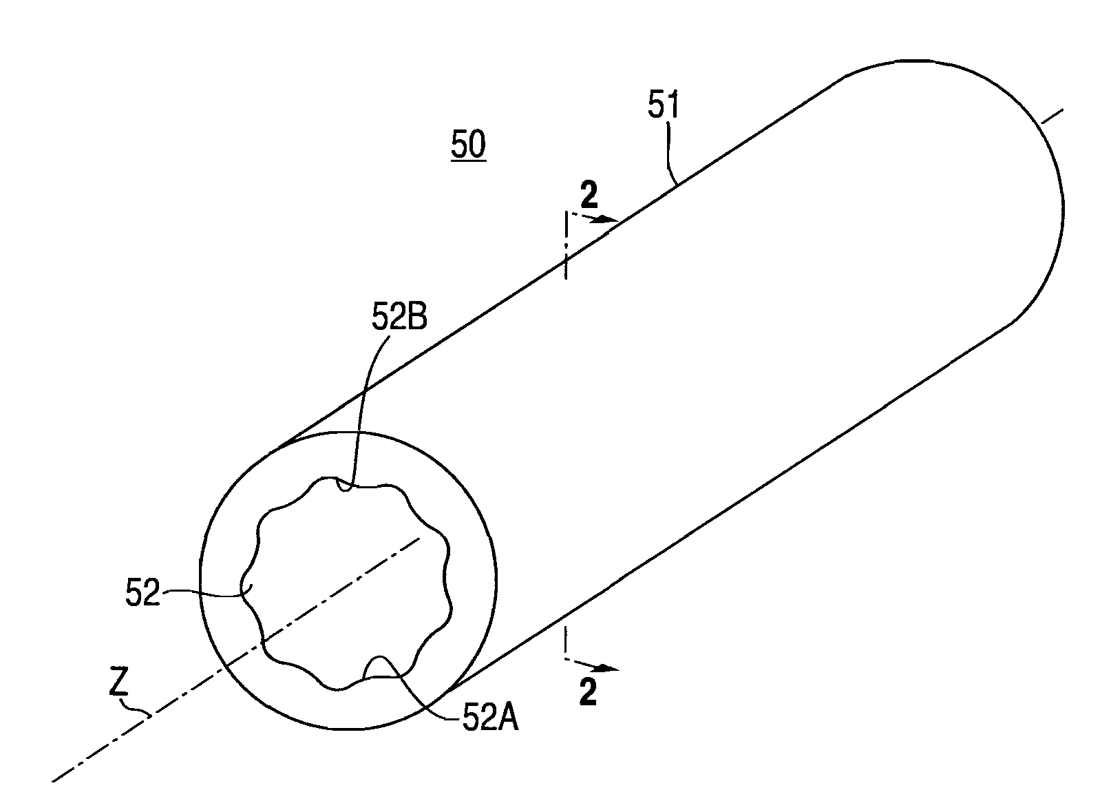
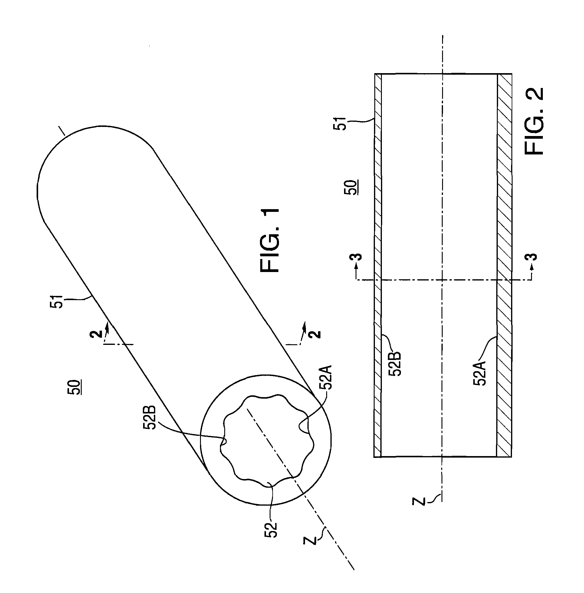
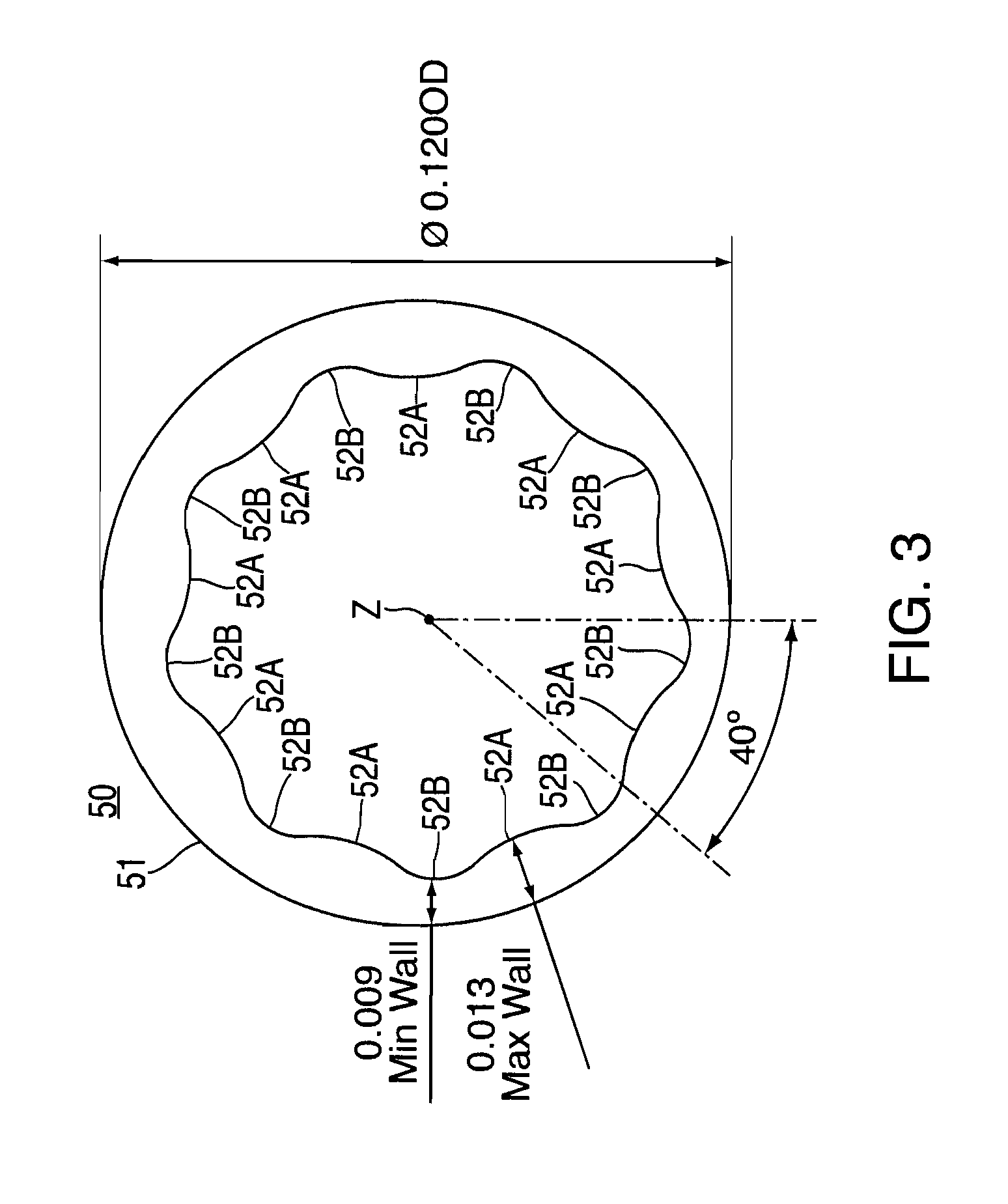
[0009]In certain preferred aspects of the present invention, the inner bearing surface includes between adjacent inwardly projecting surfaces one or more containment regions, gaps, or troughs which normally provide for a relatively open region between the inner bearing surface and the outer surface of the motion transmitting member. While applicants do not wish to be necessarily bound by or to any particular theory of operation, it is believed that the existence of such containment regions or gaps provides the assemblies and liners of the present invention with substantial advantage in certain performance characteristics. By way of one example, applicants have found that the noise production characteristics of the assemblies, that is, the noise levels produced by operation of the assembly, are substantially reduced, and that such improvements are achieved in accordance with certain embodiments of the present invention, at least in part, as a result of the presence of such gaps or containment regions. In particular, in those common embodiments in which a lubricant is included in the assembly adjacent to the motion transmitting member, it is believed that the containment region or gap provides a location in which the lubricant will be exposed less to direct frictional interface between the liner and the cable. In such situations, the containment region, gap or trough provides an area in the nature of a reservoir for the lubricant. It is believed that the presence of such a structure improves the overall performance of the assembly, at least in part, by allowing for improved longevity and performance of the lubricant. It is also believed that the preferred trough or containment structure described herein may provide beneficial properties as a direct consequence of the structure independent of the lubricant performance. For example, it is believed that since the preferred structure of the present invention provides a reduction in contact area between the liner and the motion transmitting member at any given point in the time of operation, this arrangement in accordance with the present invention will produce not only extended life of the assembly but also a reduction in the noise producing characteristics of the assemblies.
[0013]One aspect of the present invention provides cable assemblies, in particular motion transmitting cable assemblies, in which the liner portion of the assembly is in accordance with the enclosing member of the present invention. Applicants have found that the abrasion resistance and frictional efficiency of such assemblies, including over long cycle times, and potentially with high loads, can be improved relative to assemblies in which the liner is not in accordance with the present invention.

Problems solved by technology

As a result, the side walls of the cable conduit or sheath are frequently subject to intermittent and potentially severe loading, depending upon the mode of operation.
While such assemblies do produce wear of the cable conduit and its liner, the wear is generally not as severe as with the push-pull type assemblies.
In such configurations, the conduit is also subject to abrasion as a result of contact with the rotating core.

Method used


Image

  • Motion Transmitting Cable Liner and Assemblies Containing Same
  • Motion Transmitting Cable Liner and Assemblies Containing Same
  • Motion Transmitting Cable Liner and Assemblies Containing Same

Examples


example 1

[0039]A low load ambient S-test was performed to show the improved frictional efficiency of cable assemblies having liners according to the present invention. A liner was formed as in Comparative Example 1, except the inner surface was as indicted in FIGS. 2 and 3. The tubular product was subject to the low load, ambient S-test, as described in Comparative Example 1A. The initial frictional efficiency was found to be 88.5%, an increase over the initial frictional efficiency of the liner tested in Comparative Example. Also the frictional efficiency after 400,000 cycles was substantially undiminished, and ended with a value of 86.2% after 500,000 cycles of operation.

TABLE IInitialAfterFrictional50KEfficiencycycles100K200K300K400K500KComparative88.588.989.289.288.988.686.2Example 1Example 186.286.286.086.086.586.284.7

example 2

[0040]A low load ambient S-test is performed to show the improved noise production characteristics of cable assemblies having liners according to the present invention. A liner was formed as in Comparative Example 2, except the inner surface was as indicted in FIGS. 2 and 3. The tubular product was subject to the low load, ambient S-test, as described in Comparative Example 2. The noise production is found to be less than the initial noise production of the assembly in Comparative Example 2. The preferred extent of noise production is reported in Table 2 below:

TABLE 2Reduction %Reduction %Initial NoiseAfter 250KAfter 500KReduction %cyclescyclesPreferred>10%>10%>10%Noise ReductionMore Preferred>15%>15%>15%Noise ReductionEven More Preferred>25%>25%>25%Noise Reduction


PUM


Abstract

Disclosed are cable assemblies, liners for cable assemblies and methods for making same. The liner in preferred embodiments comprises bearing surface with inwardly projecting surfaces, preferably at substantially regularly spaced intervals along the inner circumference of the bearing surface.

Description

RELATED APPLICATIONS[0001]The present application is related to and claims the priority benefit of each of the following previously filed applications: U.S. provisional application 61 / 037,660 filed Mar. 18, 2008; International Application PCT / US06 / 24100, filed 21 Jun. 2006, which in turn claims priority to U.S. provisional application 60 / 694,356, filed 25 Jun. 2005; and U.S. application Ser. No. 11 / 922,870, filed 26 Dec. 2007, which is the national stage entry of the international application mentioned herein and which is currently pending. Each of the above identified applications is incorporated by reference herein as if fully set forth below.FIELD OF THE INVENTION[0002]This invention relates generally to cable assemblies and liners for cable assemblies, and more particularly to cable assemblies of the type typically used (for example in automobiles) to transmit rotary or linear motion along a predetermined path. In a particular aspect, the present invention relates to liners havi...

Claims


Application Information

Patent Timeline
IPC IPC(8): F16C1/26F16C1/24
CPCY10T74/20456F16C1/26
Inventor REYNOLDS, KIMMARINO, CHARLES P.KRAY, KEVIN
Owner MARKEL CORPORATION
Learn More