Cooling device for engine

Inactive Publication Date: 2009-09-17
TOYOTA JIDOSHA KK
View PDF3 Cites 38 Cited by
  • Summary
  • Abstract
  • Description
  • Claims
  • Application Information

AI Technical Summary

Benefits of technology

[0019]According to the present invention, if the engine is not in the cold state, the setting unit sets the flow rate to the flow rat

Problems solved by technology

Accordingly, there arises a problem of difficulty in raising a temperature of the engine.
The engine at a low temperature causes unstable combustion, which may deteriorate fuel economy.
A temperature of the cooling medium in the heater core is difficult to rise, which may fail to ensure heater performance.
Furthermore, a flow rate produced by t

Method used


Image

  • Cooling device for engine
  • Cooling device for engine
  • Cooling device for engine

Examples


first embodiment

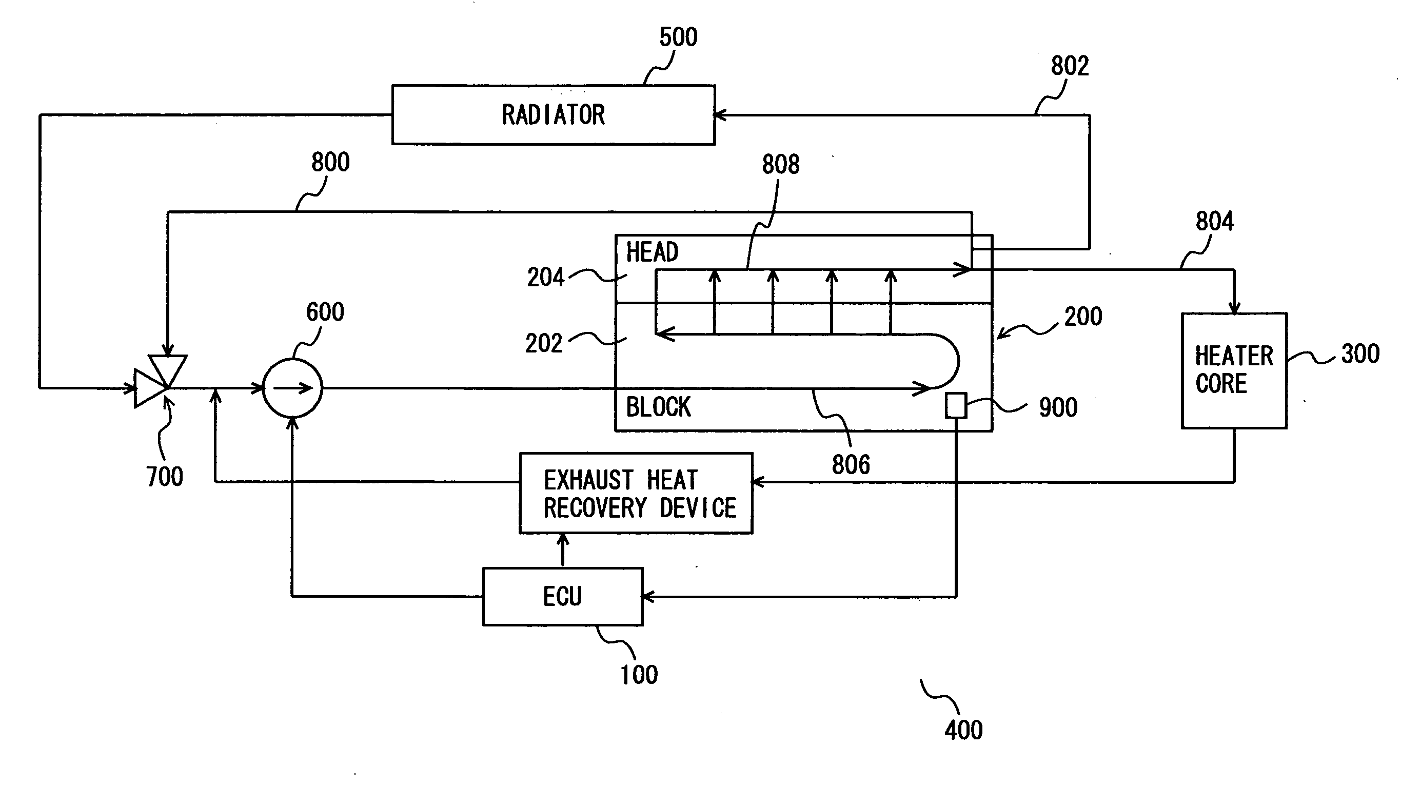
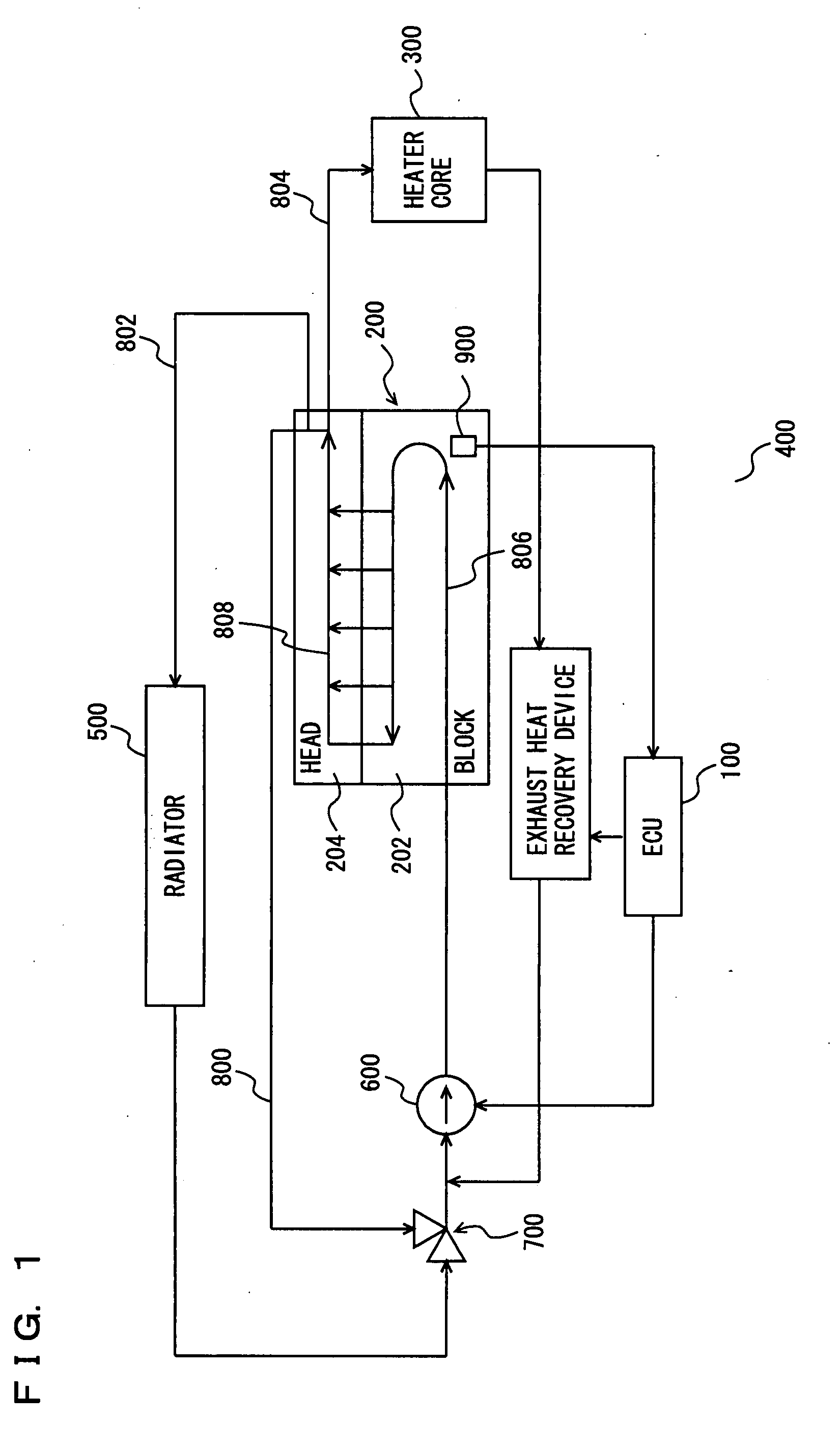
[0027]Referring to FIG. 1, a cooling device for an engine according to the present embodiment will be described. The cooling device for the engine according to the present embodiment is mounted on a vehicle, for example, and includes an Electronic Control Unit (ECU) 100, medium paths 806 and 808 provided at an engine 200, a heater core 300, an exhaust heat recovery device 400, a radiator 500, an electric water pump 600, and a thermostat 700. Engine 200 includes a cylinder block 202, and a cylinder head 204 disposed on cylinder block 202. Cylinder block 202 is provided with medium path 806, while cylinder head 204 is provided with medium path 808.

[0028]A cooling medium is supplied to engine 200 from electric water pump 600. In the present embodiment, the cooling medium refers to, for example, cooling water (i.e. coolant). However, the cooling medium is not particularly limited thereto. For example, the cooling medium may be gaseous. It is to be noted that, in the following descriptio...

second embodiment

[0059]A cooling device for an engine according to a second embodiment of the present invention will hereinafter be described. The cooling device for the engine according to the present embodiment is different from the cooling device for the engine according to the first embodiment above, in terms of a control structure of the program executed by ECU 100. Other configurations are similar to those of the cooling device for the engine according to the first embodiment above. These configurations are provided with the same reference characters and have the same functions. Accordingly, the detailed description thereof will not be repeated here.

[0060]Referring to FIG. 5, there is described a control structure of the program executed by ECU 100 in the cooling device for the engine according to the present embodiment. In the flowchart shown in FIG. 5, the same process as that in the flowchart shown in FIG. 4 described above is provided with the same step number. These processes have the sam...

third embodiment

[0070]A cooling device for an engine according to a third embodiment of the present invention will hereinafter be described. The cooling device for the engine according to the present embodiment is different from the cooling device for the engine according to the first embodiment above, in terms of a control structure of the program executed by ECU 100. Other configurations are similar to those of the cooling device for the engine according to the first embodiment above. These configurations are provided with the same reference characters, and have the same functions. Accordingly, the detailed description thereof will not be repeated here.

[0071]Referring to FIG. 6, there is described a control structure of the program executed by ECU 100 in the cooling device for the engine according to the present embodiment. In the flowchart shown in FIG. 6, the same process as that shown in the flowchart shown in FIG. 5 described above is provided with the same step number. These processes have t...


PUM


Abstract

An ECU executes a program including a step of, if an engine is not in a cold state, controlling electric power to be supplied to an electric water pump such that a flow rate requested at the engine is obtained, a step of, if the engine is in the cold state and a heater is not requested to operate, providing control such that the electric water pump is stopped, and a step of, if the engine is in the cold state and the heater is requested to operate, controlling the electric power to be supplied to the electric water pump such that the flow rate is set to the highest one of the flow rate requested at the engine, a flow rate requested at a heater core, and a flow rate requested at an exhaust heat recovery device.

Description

TECHNICAL FIELD[0001]The present invention relates to a cooling device for an engine, and particularly relates to control of a flow rate of a cooling medium for the engine at cold start.BACKGROUND ART[0002]There has conventionally been known a water-cooled engine. A cooling medium (cooling water) that has cooled the engine is brought into heat exchange with air at a radiator or a heater in an air conditioner. The air warmed at the heater through heat exchange with the cooling water is utilized for heating of a vehicle chamber. Accordingly, in order to promptly heat the vehicle chamber after the engine start, the engine is promptly warmed up to raise a temperature of the cooling medium. Furthermore, there has been known a technique of recovering thermal energy of exhaust gas emitted from the engine of a motor vehicle. For example, there has been proposed a technique of an exhaust heat recovery system, in which an exhaust heat recovery device (e.g. heat exchanger) is installed in an e...

Claims


Application Information

Patent Timeline
IPC IPC(8): F01P7/00F02G5/00F01P3/20F01P7/16F02N19/10
CPCF01N5/02F01N2240/36F01N2410/00F01N2410/06F01P3/20Y02T10/16F01P2037/02F01P2060/08F01P2060/16F01P2060/18F01P7/164Y02T10/12
Inventor SUZUKI, TAKASHI
Owner TOYOTA JIDOSHA KK
Why Eureka
Try Eureka