Exhaust gas control apparatus for internal combustion engine

a control apparatus and exhaust gas technology, applied in the direction of electrical control, machine/engine, electric control, etc., can solve the problems of inability to release nox occlusion reduction catalysts in an appropriate manner, and the frequency of execution of low flow rate reduction treatment. , to achieve the effect of suppressing deterioration of fuel economy

Active Publication Date: 2020-02-04
TOYOTA JIDOSHA KK
View PDF6 Cites 0 Cited by
  • Summary
  • Abstract
  • Description
  • Claims
  • Application Information

AI Technical Summary

Benefits of technology

[0005]The present disclosure provides an exhaust gas control apparatus for an internal combustion engine that appropriately releases and removes the NOx occluded in a NOx occlusion reduction catalyst and suppresses deterioration of fuel economy at the same time.
[0015]According to the aspect of the present disclosure, the NOx occluded in the NOx occlusion reduction catalyst can be appropriately released and removed and deterioration of fuel economy can be suppressed at the same time irrespective of the temperature of the NOx occlusion reduction catalyst.

Problems solved by technology

However, once the low flow rate reduction treatment is performed when the temperature of the NOx occlusion reduction catalyst at a time when the engine is stopped is equal to or higher than the activation temperature, the frequency of execution of the low flow rate reduction treatment declines and the NOx occluded in the NOx occlusion reduction catalyst cannot be released and removed in an appropriate manner.

Method used


Image

  • Exhaust gas control apparatus for internal combustion engine
  • Exhaust gas control apparatus for internal combustion engine
  • Exhaust gas control apparatus for internal combustion engine

Examples


first example

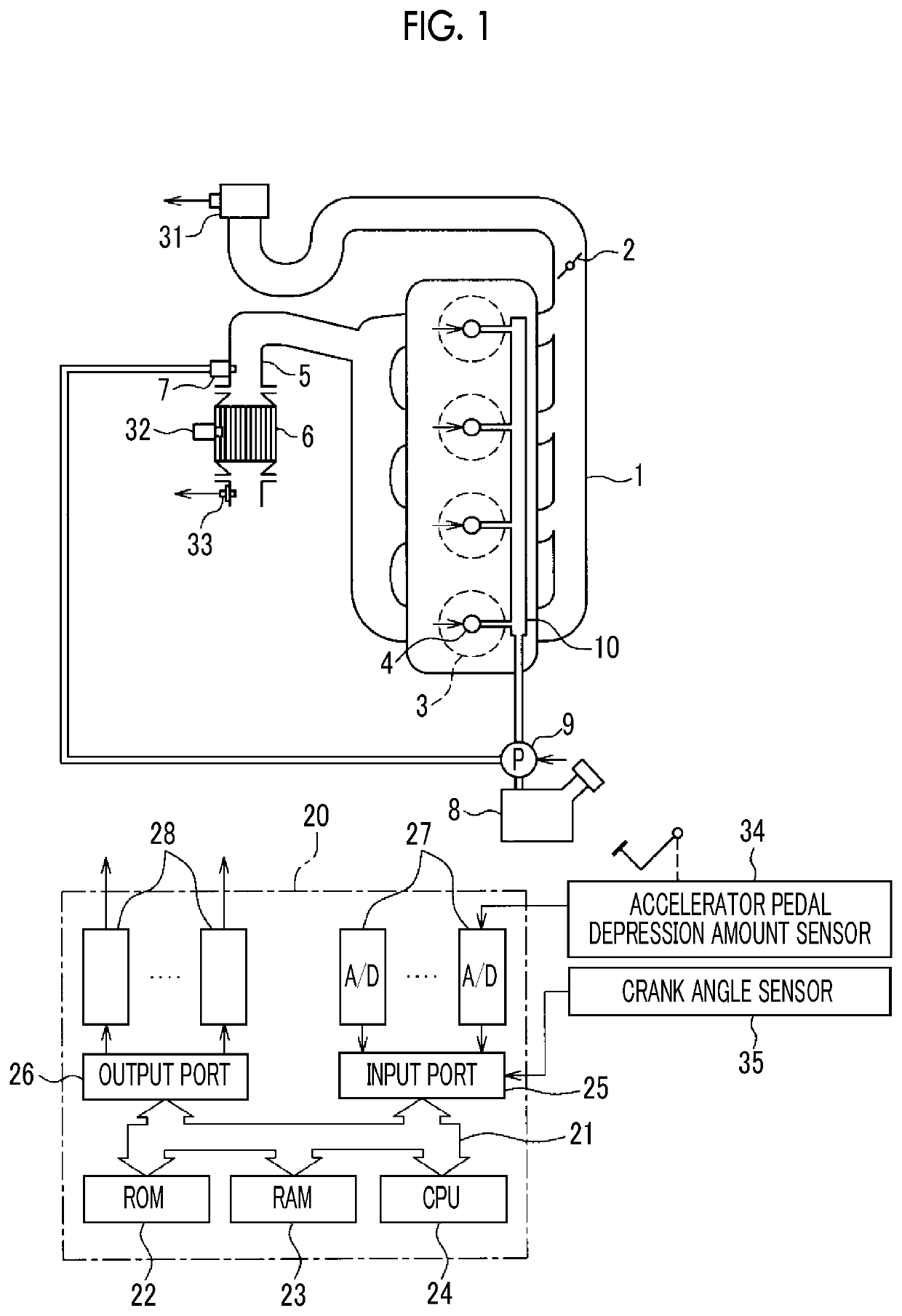
[0029]FIG. 1 is a schematic configuration diagram of an exhaust gas control apparatus for an internal combustion engine according to a first example of the present disclosure. In the first example, the internal combustion engine is a diesel engine and the internal combustion engine is provided with an intake passage 1, a throttle valve 2, a combustion chamber 3, an injector 4, an exhaust passage 5, a NOx occlusion reduction catalyst 6, and a fuel addition valve 7. The intake passage 1 and the exhaust passage 5 communicate with the combustion chamber 3 so that air flows into the combustion chamber 3 through the intake passage 1 and the air flows out from the combustion chamber 3 through the exhaust passage 5.

[0030]The throttle valve 2 is disposed in the intake passage 1. The throttle valve 2 is a valve for adjusting the amount of the air supplied into the combustion chamber 3. The air amount adjustment is performed by the opening degree of the throttle valve 2 being adjusted. In the ...

second example

[0108]An exhaust gas control apparatus for an internal combustion engine according to a second example will be described with reference to FIGS. 8 and 9. The configuration and control of the exhaust gas control apparatus for an internal combustion engine according to the second example are highly similar to those of the first example, and thus the following description will focus on how the two examples differ from each other.

[0109]As described above, the low flow rate reduction treatment is performed by the fuel addition valve 7 adding the fuel when the fuel supply from the injector 4 is stopped. When no fuel is supplied as described above includes when the ignition switch is switched to OFF as in the first example, when a vehicle decelerates, and, in a hybrid vehicle, when EV traveling is performed for the vehicle to be driven solely with the power of an electric motor for driving. Accordingly, the low flow rate reduction treatment may be performed during vehicle deceleration and ...

third example

[0122]A third example of the present disclosure using exhaust gas recirculation (EGR) will be described with reference to FIGS. 10 and 11. The configuration and control of an exhaust gas control apparatus for an internal combustion engine according to the third example are highly similar to those of the first and second examples, and thus the following description will focus on how the third example differs from the first and second examples.

[0123]FIG. 10 is a schematic diagram of the exhaust gas control apparatus for an internal combustion engine according to the third example. An exhaust recirculation device for exhaust gas recirculation is disposed in the exhaust gas control apparatus for an internal combustion engine according to the third example. The exhaust recirculation device is provided with an EGR passage 11 connecting the exhaust passage 5 and the intake passage 1 to each other and an EGR valve 12 for adjusting the passage sectional area of the EGR passage 11 in the EGR ...


PUM


Abstract

An exhaust gas control apparatus includes a fuel injection device, a NOx occlusion reduction catalyst, a fuel addition valve, an inflow gas adjustment device, and an electronic control unit. The electronic control unit executes a low flow rate reduction treatment for removing NOx occluded in the NOx occlusion reduction catalyst after fuel supply from the fuel injection device is stopped. The electronic control unit controls the inflow gas adjustment device such that a ratio of oxygen to the fuel added to the NOx occlusion reduction catalyst at a time when a temperature of the NOx occlusion reduction catalyst is below an activation temperature becomes higher than a ratio of oxygen to the fuel added to the NOx occlusion reduction catalyst at a time when the temperature of the NOx occlusion reduction catalyst is equal to or higher than the activation temperature during the low flow rate reduction treatment.

Description

INCORPORATION BY REFERENCE[0001]The disclosure of Japanese Patent Application No. 2017-123628 filed on Jun. 23, 2017 including the specification, drawings and abstract is incorporated herein by reference in its entirety.BACKGROUND1. Technical Field[0002]The present disclosure relates to an exhaust gas control apparatus for an internal combustion engine.2. Description of Related Art[0003]An exhaust gas control apparatus for an internal combustion engine is known that is provided with a NOx occlusion reduction catalyst occluding nitrogen oxide (NOx) contained in exhaust gas when the air-fuel ratio of the exhaust gas is lean (air-fuel ratio larger than a stoichiometric air-fuel ratio) and releasing the occluded NOx and removing the occluded NOx by reducing the occluded NOx when the air-fuel ratio of the exhaust gas is rich (air-fuel ratio smaller than the stoichiometric air-fuel ratio). An exhaust gas control apparatus for an internal combustion engine is known that allows exhaust gas ...

Claims


Application Information

Patent Timeline
Patent Type & Authority Patents(United States)
IPC IPC(8): F01N3/20F02D41/00F01N3/08F02D41/02F02D9/02
CPCF02D41/0055F01N3/0842F02D41/0275F01N3/0871F01N3/0814F02D9/02F02D2009/0276F02D2250/36F01N2900/08F01N2900/1404F02D2200/0806F02D2200/0802F01N3/36F01N9/00F02D41/0002F02D41/3005F01N2570/14F01N2430/08F01N2430/06F01N2900/0412F01N2900/1602Y02T10/40F01N3/206F01N11/002F01N11/007F01N2560/025F01N2560/06F01N2610/03
Inventor UMEMOTO, KAZUHIROMORI, TOSHIHIRONISHIOKA, HIROMASA
Owner TOYOTA JIDOSHA KK
Why Eureka
Try Eureka