O3 production apparatus and exhaust gas purification system for internal combustion engine

Inactive Publication Date: 2010-03-18
TOYOTA JIDOSHA KK
View PDF11 Cites 0 Cited by
  • Summary
  • Abstract
  • Description
  • Claims
  • Application Information

AI Technical Summary

Benefits of technology

[0021]Supply of O3 to the filter can promote oxidation of PM in the filter. Therefore, according to the above-described exhaust gas purification system, removal of PM from the filter can be promoted.
[

Problems solved by technology

This may lead to deterioration of the fuel economy.
When the operation state of the internal combustion engine is a de

Method used


Image

  • O3 production apparatus and exhaust gas purification system for internal combustion engine
  • O3 production apparatus and exhaust gas purification system for internal combustion engine
  • O3 production apparatus and exhaust gas purification system for internal combustion engine

Examples


embodiment 1

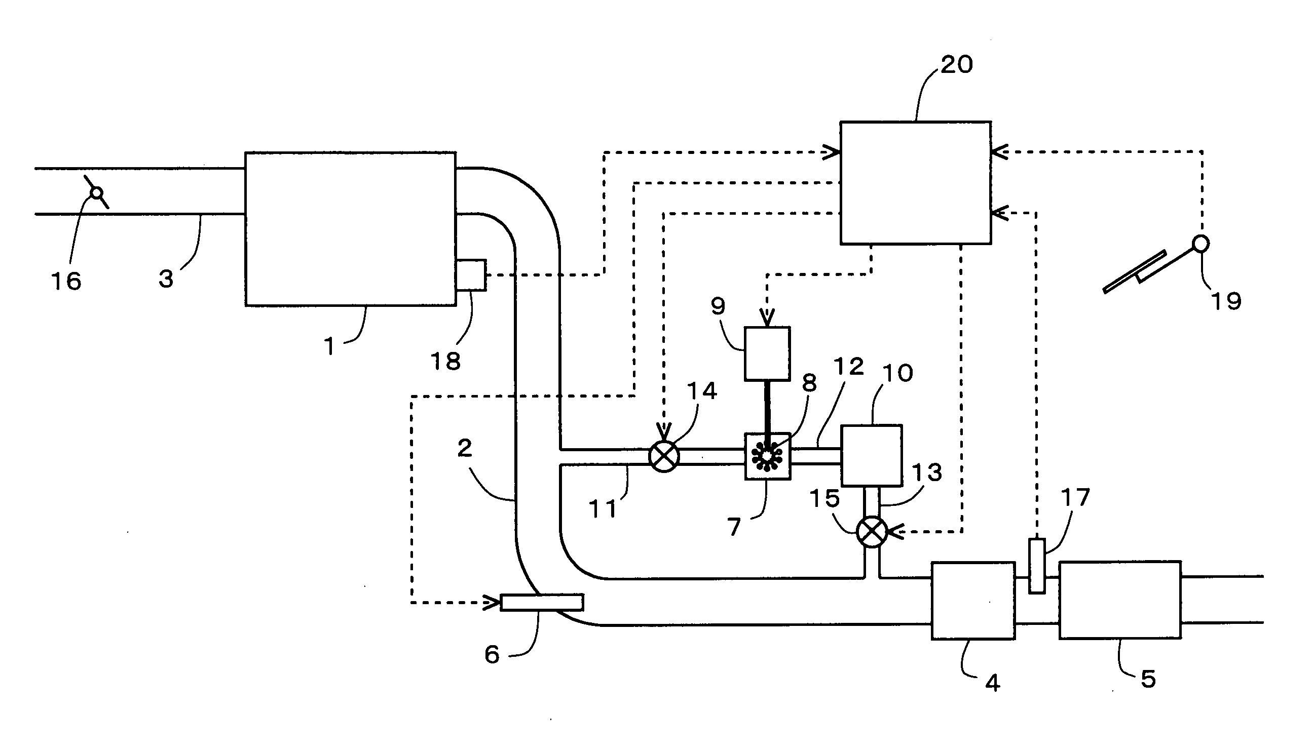
[0032]Here, a description will be made of an exemplary case in which the present invention is applied to a diesel engine for driving a vehicle. FIG. 1 is a diagram showing the general configuration of an air-intake and exhaust system of an internal combustion engine according to this embodiment.

[0033]The internal combustion engine 1 is a diesel engine for driving a vehicle. The internal combustion engine 1 is connected with an intake passage 3 and an exhaust passage 2. A throttle valve 16 is provided in the intake passage 3. An NOx catalyst 4 is provided in the exhaust passage 2. In addition, a filter 5 is provided in the exhaust passage 2 downstream of the NOx catalyst 4.

[0034]A fuel addition valve 6 that adds fuel serving as a reducing agent to the exhaust gas is provided in the exhaust passage 2 upstream of the NOx catalyst 4. A temperature sensor 17 that senses the temperature of the exhaust gas is provided between the NOx catalyst 4 and the filter 5 in the exhaust passage 2.

[00...

embodiment 2

[0059]FIG. 4 is a diagram showing the general configuration of an air-intake and exhaust system of an internal combustion engine according to this embodiment. In this embodiment, the O3 production apparatus 7 is connected with one end of a fourth communication passage 21. The other end of the fourth communication passage 21 is connected to the exhaust passage 2 at a position upstream of the NOx catalyst 4. The fourth communication passage 21 is provided with a third valve 22.

[0060]If the third valve 22 is opened when O3 is being produced by the O3 production apparatus 7, the fourth communication passage 21 is opened, and O3 produced in the O3 production apparatus 7 is supplied to the exhaust gas flowing in the exhaust passage 2. The quantity of supplied to the exhaust gas is controlled by controlling the opening degree of the third valve 22. The third valve 22 is electrically connected to the ECU and controlled by the ECU 20. The configuration other than described above is the same ...

embodiment 3

[0071]FIG. 6 is a diagram showing the generation configuration of an air-intake and exhaust system of an internal combustion engine according to this embodiment. In this embodiment, the internal combustion engine 1 is mounted on a hybrid vehicle that can selectively use, as the driving power, one or both of the power output of the internal combustion engine 1 and the power output of a motor generator 23. The motor generator 23 is electrically connected with a battery 9. The motor generator 23 can apply voltage to a plasma generation apparatus 8 of an O3 production apparatus 7. The motor generator 23 is electrically connected with an ECU 20 and controlled by the ECU 20. The configuration other than described above is the same as the general configuration of the air-intake and exhaust system of the internal combustion engine according to embodiment 1, therefore like elements will be denoted by like reference numerals, and a description thereof will be omitted.

3 Production Method>

[0072...


PUM

PropertyMeasurementUnit
Temperatureaaaaaaaaaa

Abstract

An object of the present invention is to produce O3 to be supplied to the exhaust gas of an internal combustion engine while suppressing deterioration of the fuel economy. An O3 production apparatus according to the present invention is an O3 production apparatus that produces O3 to be supplied to the exhaust gas of an internal combustion engine by generating a plasma, when the operation state of the internal combustion engine is a decelerating operation state in which the engine load becomes lower.

Description

TECHNICAL FIELD[0001]The present invention relates to an O3 production apparatus that produces O3 to be supplied to the exhaust gas of an internal combustion engine and to an exhaust gas purification system for an internal combustion engine.BACKGROUND ART[0002]An O3 production apparatus that produces O3 to be supplied to the exhaust gas of an internal combustion engine by generating a plasma has been known. Supply of O3 produced by such an O3 production apparatus to the exhaust gas promotes oxidation of NO in the exhaust gas, whereby NO can be changed into NO2. NO2 is stored more easily in an NOx storage reduction catalyst (which will be simply referred to as an “NOx catalyst” hereinafter) as compared to NO. Therefore, in the case where an NOx catalyst is provided in the exhaust passage of the internal combustion engine, changing NO in the exhaust gas into NO2 can promote storage of NOx in the NOx catalyst.[0003]Furthermore, in the case where a particulate filter (which will be simp...

Claims


Application Information

Patent Timeline
IPC IPC(8): F01N9/00F01N3/10
CPCB01D53/9409F01N2610/03B01D53/9495B01D53/96B01D2251/104B01D2255/91B01D2258/012C01B13/10F01N3/023F01N3/0814F01N3/0842F01N2240/28F01N2240/38F01N2250/02B01D53/944
Inventor TSUJIMOTO, KENICHIHIROTA, SHINYA
Owner TOYOTA JIDOSHA KK
Why Eureka
Try Eureka