Fluid transfer device

a technology of transfer device and fluid, which is applied in the direction of operating means/releasing devices of valves, machines/engines, and positive displacement liquid engines, etc., can solve the problems of increasing the risk of contamination of the entire system, not always being able to completely close the processing system, and using steam

Active Publication Date: 2009-09-17
MILLIPORE CORP
View PDF99 Cites 49 Cited by
  • Summary
  • Abstract
  • Description
  • Claims
  • Application Information

AI Technical Summary

Benefits of technology

[0012]In another embodiment, the present invention relates to a disposable fluid transfer device for use in traditional stainless steel processing systems or disposable processing systems. The fluid transfer device of the present invention provides a steam sterilizing mating point between the transfer device and an upstream component, and a sterilizeable mating point between the transfer device and a downstream component. Additionally, the transfer device can be conveniently removed from the processing system and discarded after use, thereby not requiring a cleaning regiment.
[0013]In another embodiment, the present invention also relates to disposable large scale fluid transfer devices for the integration of large scale disposable upstream and / or downstream assemblies into traditional stainless steel systems or disposable systems. The fluid transfer device of the present invention provides a steam sterilizing mating point between the transfer device and an upstream component, and a sterilizeable mating point between the transfer device and a downstream component. Additionally, the transfer device can be conveniently removed from the processing system and discarded after use, thereby not requiring any cleaning regiment.

Problems solved by technology

However, completely closed processing systems are not always possible since there is a need for the introduction or removal of materials from the process stream in order to add components of the product, such as media or buffers to a bioreactor; withdraw samples from the process stream to check for microbial contamination, quality control, process control, etc; and to collect the product into its final container such as vials, syringes, sealed boxes, bottles and the like.
However, several disadvantages exist with the use of steam.
This increases the risk of contamination of the entire system.
Also, the high temperatures and pressure differentials associated with steam make the selection of filter materials and other components difficult and limited.
Additionally, accidental pressure differential at high temperatures can cause a filter, membrane or other non-steel component to fail.
The validation process and the required cleaning regiment of a previously used system are expensive and time consuming, typically taking up to 1 to 2 years for approval.
In addition, certain components are difficult to adequately clean after use in preparation for their next use.

Method used


Image

  • Fluid transfer device
  • Fluid transfer device
  • Fluid transfer device

Examples


Embodiment Construction

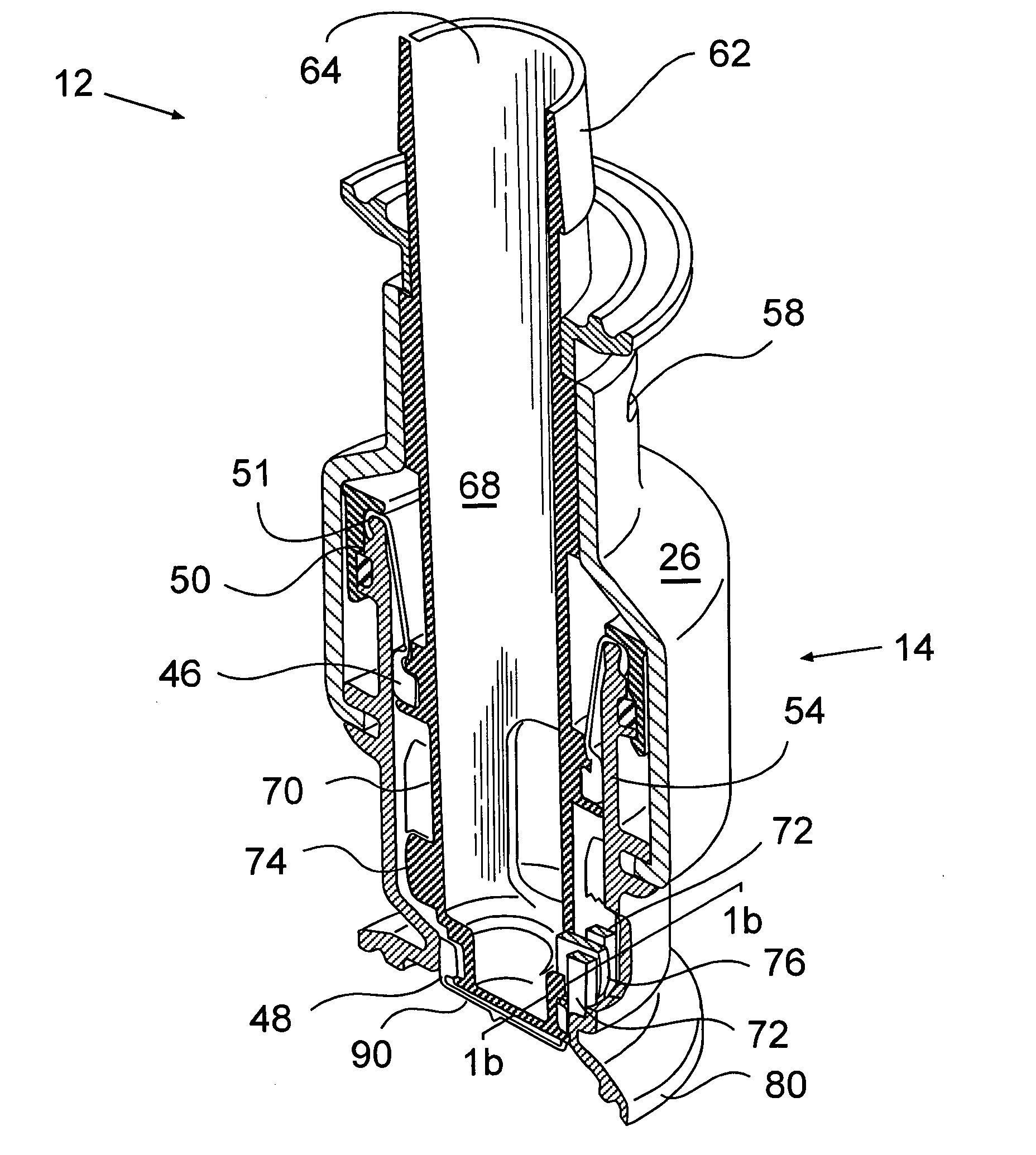
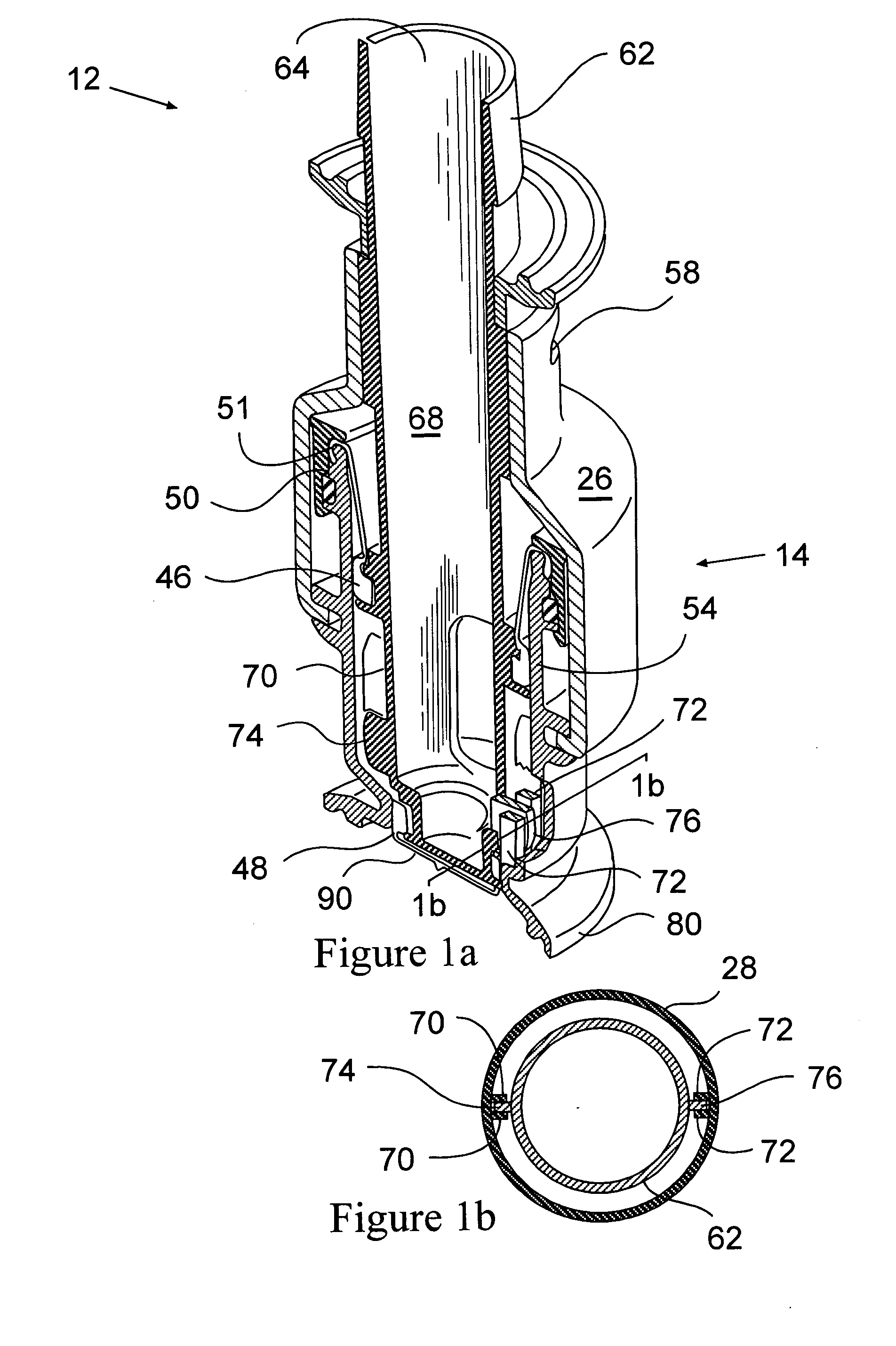
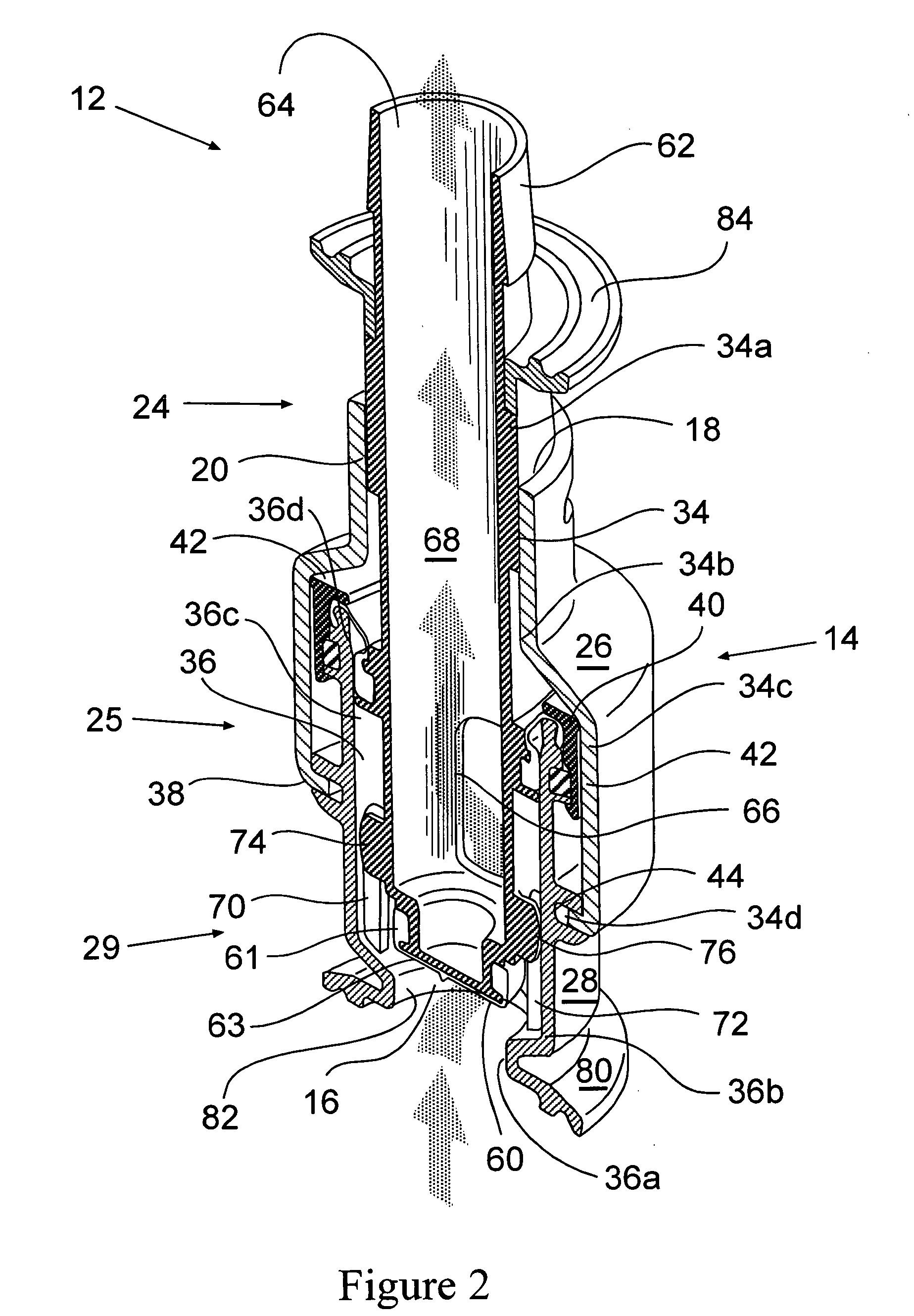
[0020]In general, the present invention is a sterile fluid transfer device, such as a flow-through connector or valve, wherein the fluids are liquids and / or gases. In one embodiment, the fluid transfer device has a body, a bore located in the interior of the body, and a linearly movable plunger contained within the bore. The body is formed from a first and a second section. The first section has a first end containing a first opening and a termination attachment component, such as a flange or the like surrounding the first opening for attaching the body to an upstream component(s). The second section has a second end containing a second opening, wherein the bore connects the first and second openings. The first section rotates around a portion of the second section.

[0021]The linearly movable plunger includes a first end containing a first opening, a second end containing a second opening, a fluid channel located in the interior of the plunger connecting the first and second openings...


PUM


Abstract

A disposable device for the sterile transfer of fluids, such as liquids or gases, includes a body, a bore formed through at least a portion of the interior of the body, and a linearly moveable plunger contained within the bore. The body is formed from a rotating section and a stationary section. Partial rotation of the rotating section around a portion of the stationary section and the plunger drives the plunger linearly within the bore, opening and closing the device. The plunger includes at least a first and a second opening, and a fluid channel in the interior of the plunger connecting the first and second openings forming a fluid pathway to downstream components when the device is open. A termination component at one end of the plunger connects to a downstream component. A flange at one end of the body attaches to an upstream component. When the device is closed, the upstream end of the plunger is in alignment with the upstream flange of the body, forming a steamable sterilized in place face and a sterile barrier.

Description

CROSS-REFERENCE RELATED APPLICATIONS[0001]This application claims the benefit of U.S. Provisional Patent Application No. 61 / 003,364, filed on Nov. 16, 2007 the entire contents of which are incorporated by reference herein.[0002]The present invention relates to a fluid transfer device. More particularly, it relates to a disposable, sterile, fluid transfer device in the form of a flow-through connector or valve for use in the pharmaceutical and biopharmaceutical industries.BACKGROUND OF THE INVENTION[0003]In the pharmaceutical, biotechnology and even food, beverage and cosmetic industries, it is often desired to provide large scale processing systems that are capable of handling fluids in a sterile manner. These large scale processing systems are designed to prevent unwanted and often dangerous organisms, such as bacteria, as well as unwanted and potentially harmful environmental contaminants, such as dust, dirt and the like from entering into the process stream and / or end product. In...

Claims


Application Information

Patent Timeline
Patent Type & Authority Applications(United States)
IPC IPC(8): F15C3/16
CPCA61M39/22F04B39/0005F16K31/528F16K1/12Y10T137/0391Y10T137/8593Y10T137/85986
Inventor HARTNETT, JEFFLOFVING, ALFHULTQUIST, LARSDAVIDSSON, JANMYHRBERG, LENNART
Owner MILLIPORE CORP
Why Eureka
Try Eureka