
Plug Structure of a Coupler

a coupler and plug technology, applied in the direction of couplings, functional valve types, transportation and packaging, etc., can solve the problems of hard and inferior elasticity, liable to be damaged, and inability to expect such damage, and achieve the effect of easy removal

Inactive Publication Date: 2009-09-17
TOYO SEIKAN KAISHA LTD +1
View PDF5 Cites 1 Cited by
  • Summary
  • Abstract
  • Description
  • Claims
  • Application Information

AI Technical Summary

Benefits of technology

[0011]It is therefore desired to develop a plug of a coupler which can be connected accurately and stably by a simple operation which, when an excessive force exceeding a normal range of use is applied in the connected state, can maintain a sealed state and can be used safely even if the plug is broken.
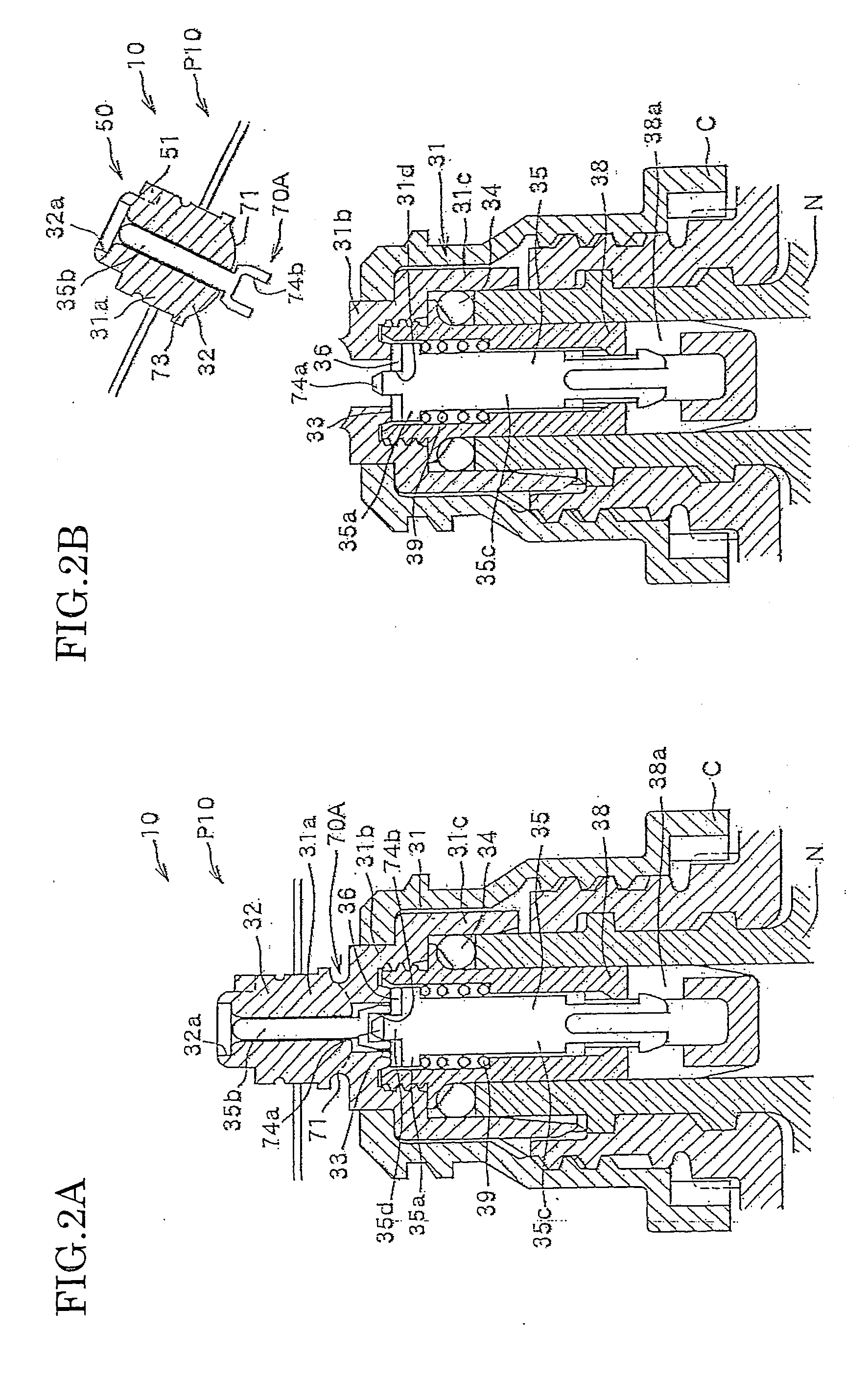
[0037]According to this aspect of the invention, since a gripping portion is provided in a dividing surface between the plug main body and the projecting connecting portion for enabling taking out of the projecting connecting portion after breaking and separating of the projecting connecting portion, even if the projecting connecting portion remains on the side of the socket in the fitted and connected state, the remaining portion can be taken out easily by gripping portion and the socket can be fitted and connected with another plug.

Problems solved by technology

These materials, however, are hard and inferior in elasticity and, therefore, are liable to be damaged when an excessive force is applied in the connected state.
It is particularly a problem that where such damage will take place cannot be expected.

Method used


Image

  • Plug Structure of a Coupler
  • Plug Structure of a Coupler
  • Plug Structure of a Coupler

Examples


Embodiment Construction

[0043]Embodiments of the present invention will now be described with reference to the accompanying drawings.

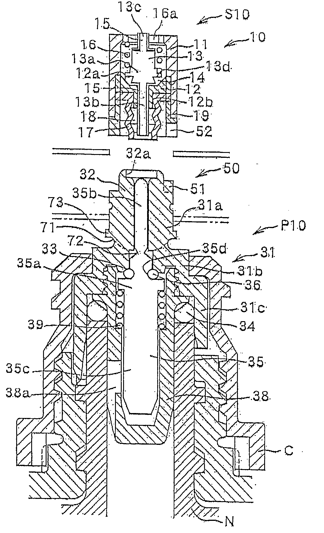
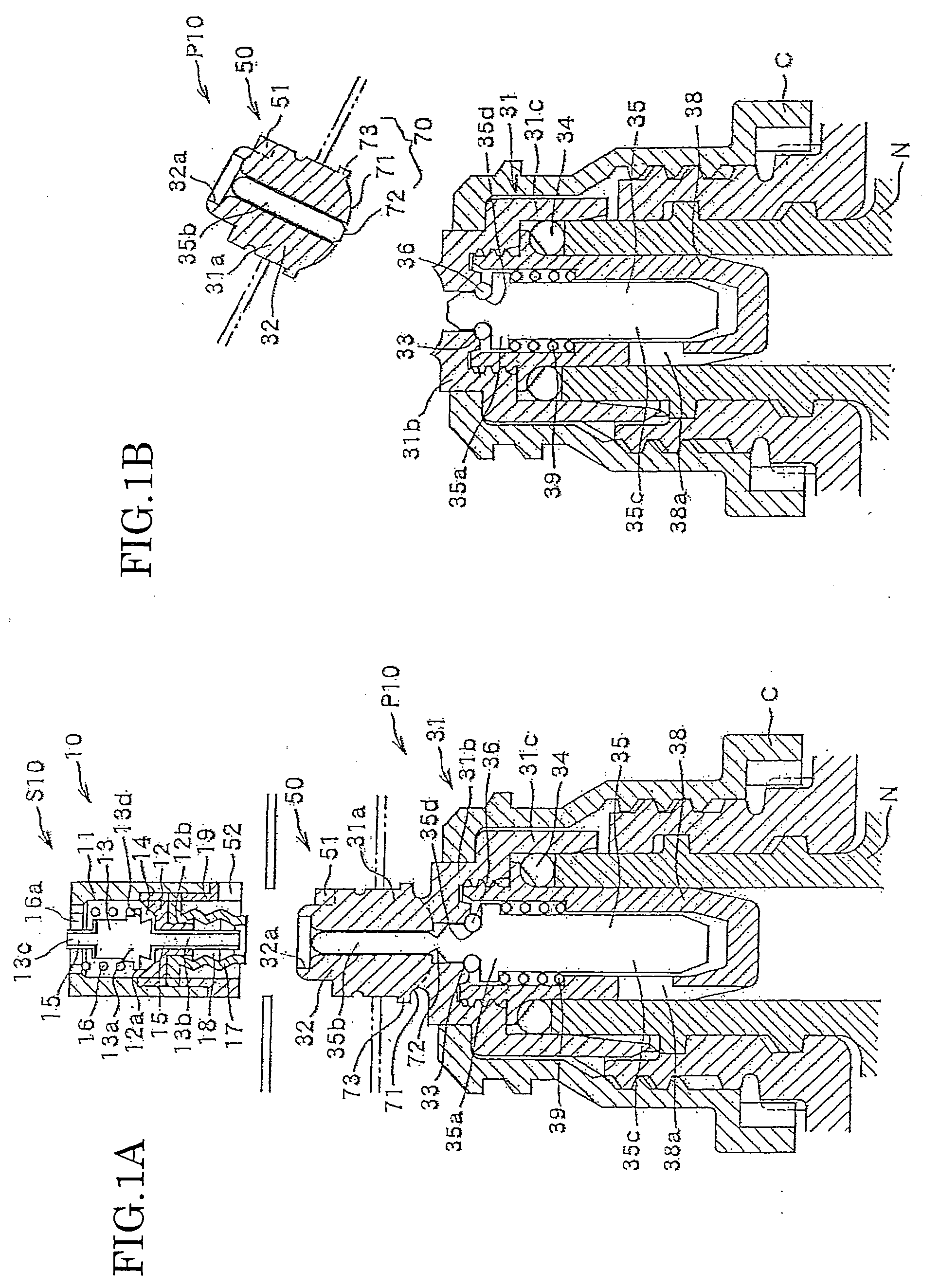
[0044]FIG. 1 are a vertical sectional view showing an embodiment of a plug structure of a coupler according to the invention with a socket and a vertical sectional view of a broken state of the plug structure.

[0045]Description will first be made about a basic structure of a coupler 10 to which the plug structure of a coupler of the present invention is applied. The coupler 10 is composed of a socket S10 and a plug P10 which is fitted and connected with the socket S10. The socket S10 is provided, for example, on the side of a main body of a methanol fuel cell and the plug P10 is provided on the side of a cartridge as a methanol container for communicating each other to supplement fuel to the fuel cell main body or to replace the cartridge itself.

[0046]As a material of a main part of the socket S10 which is fitted and connected with the plug P10 of the coupler 10 can be used me...


PUM


Abstract

A projecting connecting portion 32 which is fitted to a socket S10 and a valve seat 33 are provided in a plug main body 31 of a plug P10. The valve main body 31 having a valve head 35 which is urged to the valve seat 33 for sealing is provided in the plug main body 31 and the projecting connecting portion 32. Breaking starting portions 71 and 72 are provided in at least a part of the projecting connecting portion 32 and / or the valve stem 35b. A position at which breaking occurs when an excessive force exceeding a normal range of use is applied is set at a predetermined position whereby, when breakage occurs, the sealed state between the valve seat 33 and the valve head 35a can be maintained.

Description

TECHNICAL FIELD[0001]This invention relates to a plug structure of a coupler consisting of a socket and a plug which are detachably fitted and connected together, which can be connected accurately by a simple operation in a case where liquid or other material is shifted from a container to a container on the main body side or where a container itself is replaced and which can maintain a sealed state when an excessive force is applied in the connected state. More particularly, this invention relates to a plug structure of this type which is suitable for use as a plug of a cartridge type container of a methanol fuel cell.BACKGROUND ART[0002]There are cases where it is necessary to supplement liquid such as a liquid material which decreases as a machine or instrument is driven or used and, in such cases, liquid such as a liquid material is supplemented by connecting a cartridge container to a container provided on the side of the machine or instrument, or by replacing a container provi...

Claims


Application Information

Patent Timeline
IPC IPC(8): F16K15/00
CPCF16L37/36F16L55/1015Y02E60/50H01M8/04201F23K5/14Y10T137/6086B65D83/00H01M8/04
Inventor YOSHIHIRO, KENJIYAMAMORI, YOUTAKAHASHI, KENICHI
Owner TOYO SEIKAN KAISHA LTD
Learn More