
Radial flow valve

a flow valve and radial flow technology, applied in the direction of fluid removal, wellbore/well accessories, construction, etc., can solve the problems of requiring more time and extra trips to install the isolation assembly, requiring more time-consuming methods with less flexibility and reliability, and prior system installation within the wellbore. requiring more time-consuming methods

Active Publication Date: 2009-09-17
SUPERIOR ENERGY SERVICES LLC
View PDF11 Cites 11 Cited by
  • Summary
  • Abstract
  • Description
  • Claims
  • Application Information

AI Technical Summary

Benefits of technology

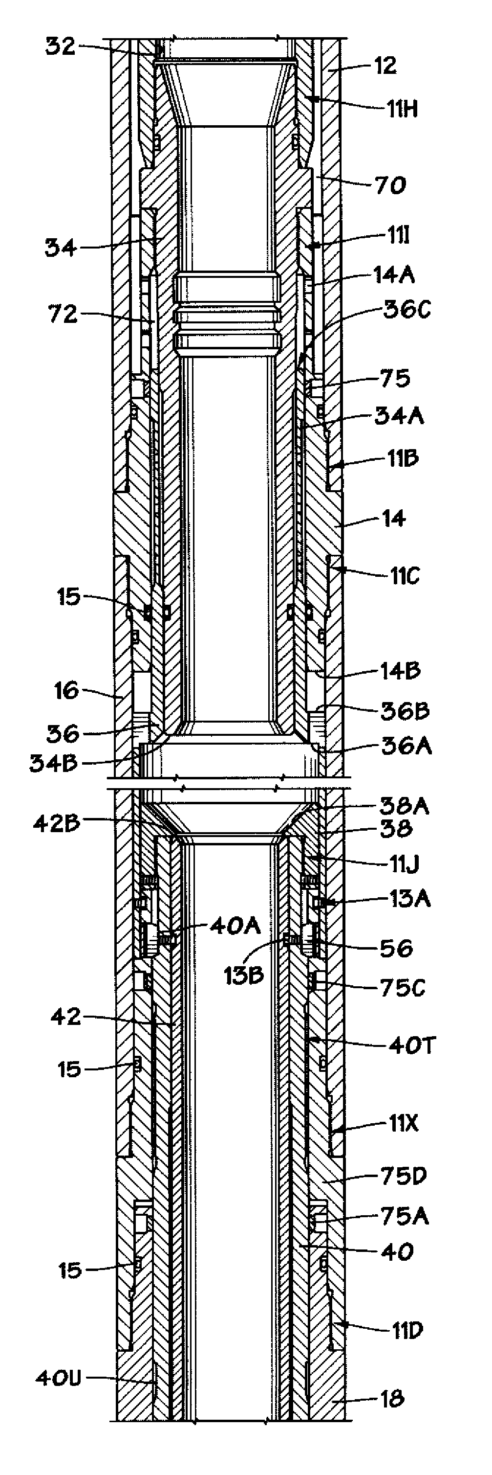
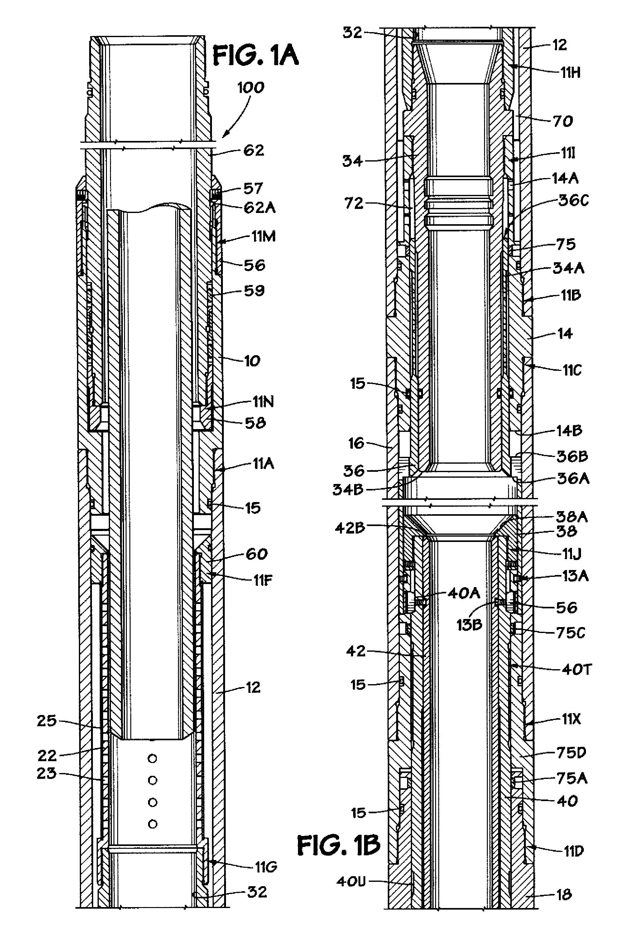
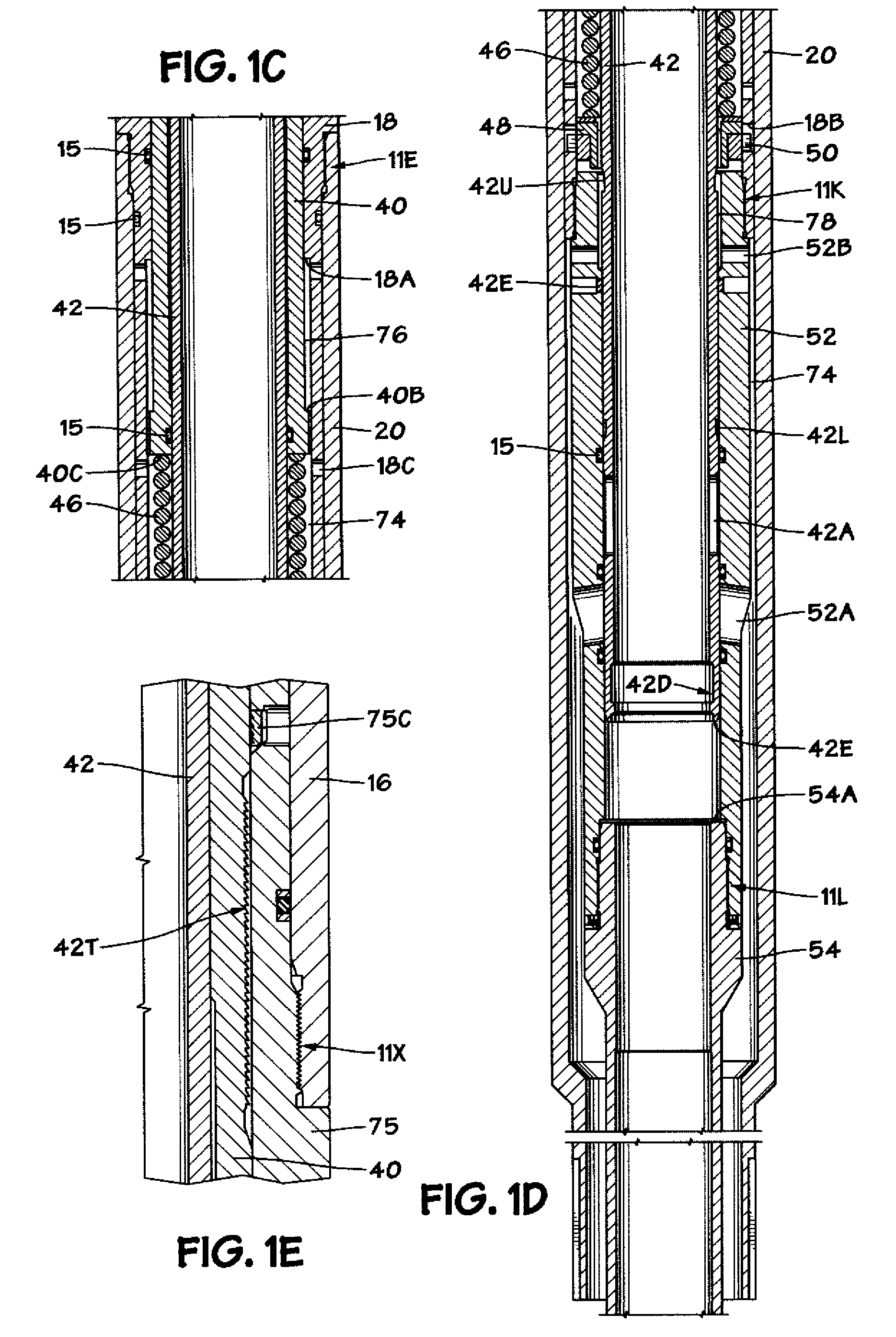
[0011]In one illustrative embodiment, a method is disclosed which includes positioning a radial flow valve in a subterranean well bore having an upper zone pressure and a lower zone pressure, increasing a pressure within the valve to a value above the upper zone pressure to release a first piston within the valve and, after releasing the first piston, reducing the pressure within the valve to a value that is less than the lower zone pressure to thereby cause a second piston within the valve to move and thereby permit fluid flow through the valve.

Problems solved by technology

Early prior art isolation systems involved intricate positioning of tools which were installed downhole after the gravel pack.
Certain disadvantages have been identified with the systems of the prior art.
For example, prior conventional isolation systems have had to be installed after the gravel pack, thus requiring greater time and extra trips to install the isolation assemblies.
In addition, the installation of prior systems within the wellbore require more time-consuming methods with less flexibility and reliability than a system which is installed at the surface.
Prior art systems that do not isolate the formation between tool trips suffer significant fluid losses.
However, the extension of the washpipe through the isolation valve presents a potential failure point.
For example, the washpipe may become lodged in the isolation string below the isolation valve due to debris or settled sand particles.
Also, the shifting tool may improperly mate with the isolation valve and become lodged therein.

Method used


Image

  • Radial flow valve
  • Radial flow valve
  • Radial flow valve

Examples


Embodiment Construction

[0021]Illustrative embodiments of the present subject matter are described below. In the interest of clarity, not all features of an actual implementation are described in this specification. It will of course be appreciated that in the development of any such actual embodiment, numerous implementation-specific decisions must be made to achieve the developers' specific goals, such as compliance with system-related and business-related constraints, which will vary from one implementation to another. Moreover, it will be appreciated that such a development effort might be complex and time-consuming, but would nevertheless be a routine undertaking for those of ordinary skill in the art having the benefit of this disclosure.

[0022]The present subject matter will now be described with reference to the attached figures. The words and phrases used herein should be understood and interpreted to have a meaning consistent with the understanding of those words and phrases by those skilled in th...


PUM


Abstract

A radial flow valve is disclosed which includes a plurality of flow openings, a first piston and a second piston, the first and second pistons being independently actuable relative to one another, and a sleeve operatively coupled to the second piston, the sleeve adapted to be positioned so as to cover the plurality of flow openings. A method is also disclosed which includes positioning a radial flow valve in a subterranean well bore having an upper zone pressure and a lower zone pressure, increasing a pressure within the valve to a value above the upper zone pressure to release a first piston within the valve and, after releasing the first piston, reducing the pressure within the valve to a value that is less than the lower zone pressure to thereby cause a second piston within the valve to move and thereby permit fluid flow through the valve.

Description

BACKGROUND OF THE INVENTION[0001]1. Field of the Invention[0002]The present invention is generally directed to downhole tools employed in oil and gas wells, and, more particularly, to a radial flow valve.[0003]2. Description of the Related Art[0004]Early prior art isolation systems involved intricate positioning of tools which were installed downhole after the gravel pack. These systems are exemplified by a commercial system which at one time was available from Baker. This system utilized an anchor assembly which was run into the wellbore after the gravel pack. The anchor assembly was released by a shearing action and subsequently latched into position.[0005]Certain disadvantages have been identified with the systems of the prior art. For example, prior conventional isolation systems have had to be installed after the gravel pack, thus requiring greater time and extra trips to install the isolation assemblies. Also, prior systems have involved the use of fluid loss control pills aft...

Claims


Application Information

Patent Timeline
Patent Type & Authority Applications(United States)
IPC IPC(8): E21B34/06
CPCE21B34/10E21B2034/007E21B43/04E21B2200/06
Inventor ROSS, RICHARD J.
Owner SUPERIOR ENERGY SERVICES LLC
Learn More