Adjustable hydraulic damper for vehicles

Inactive Publication Date: 2009-09-17
HUNG SHENG FU
View PDF6 Cites 2 Cited by
  • Summary
  • Abstract
  • Description
  • Claims
  • Application Information

AI Technical Summary

Benefits of technology

[0007]The another purpose of the present invention is to enable circulating oil feed of oil tank based on the extrusion principle of piston and piston rod in the hydraulic damper, without the thrusting of any pump. Other than kinetic energy that's converted and supplied continuously to the vehicle components, it is possible to save the cost of the mechanism and increase its commercial value.

Problems solved by technology

And, the vehicles are also a major contributing factor to oil consumption.
However, due to poorer performance as compared with oil, the existing alternative energy resources are provided only as an auxiliary means, of which oil-electricity conversion is a preferred option.

Method used


Image

  • Adjustable hydraulic damper for vehicles
  • Adjustable hydraulic damper for vehicles
  • Adjustable hydraulic damper for vehicles

Examples


Embodiment Construction

[0014]The structural composition, technical means and efficacy of the present invention will be more readily understood with reference to the accompanying drawings.

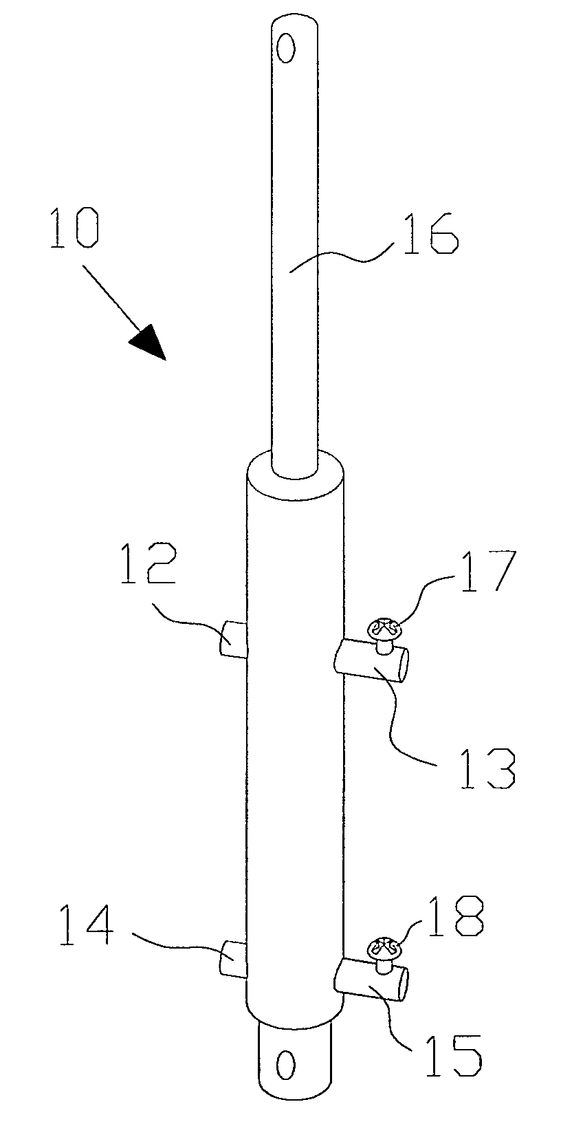
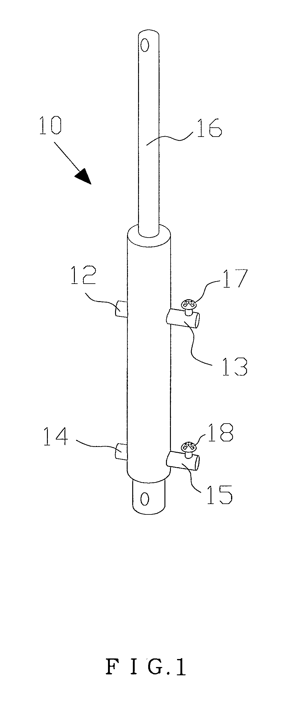
[0015]Referring to FIG. 1 (a perspective view), a set of inlet and outlet check valves 12, 13, 14, 15 are separately arranged at upper and lower sides of the hydraulic damper body 10; and the outlet valves 13, 15 are separately fitted with adjusting screws 17, 18; the piston 11 and piston rod 16 of hydraulic damper body 10 are shiftable linkage components.

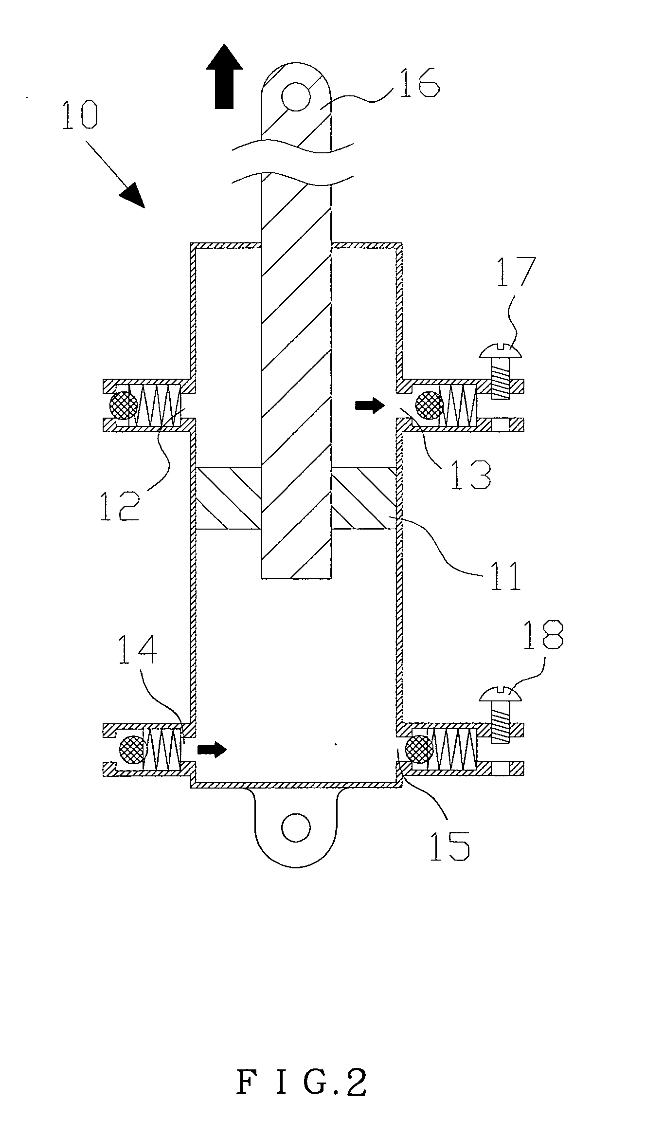
[0016]Referring to FIGS. 2 and 3 (schematic views of oil inlet and outlet), when the piston 11 and piston rod 16 of the hydraulic damper body 10 squeeze upwards, the upper inlet valve 12 and lower outlet valve 15 are in a closed state, the oil liquid is output if upper outlet valve 13 is opened, and then flows into hydraulic damper body 10 if the lower inlet valve 14 is opened simultaneously; conversely, when the piston 11 and piston rod 16 of the hydraulic damper body 1...


PUM


Abstract

The present invention provides an adjustable hydraulic damper for vehicles, which enables the running vehicle to generate kinetic energy through the extrusion of piston and piston rod in the hydraulic damper, thus allowing for circulating supply of high-pressure oil and providing kinetic energy to the vehicles under the control of inlet and outlet check valves installed on both sides of the hydraulic damper.

Description

BACKGROUND OF INVENTION[0001](1). Field of the Invention[0002]The present invention relates generally to an adjustable hydraulic damper for vehicles, and more particularly to an innovative one which allows for oil compression and output through the extrusion of piston and piston rod in the hydraulic damper, thus generating continuously kinetic energy for the vehicle applications.[0003](2). Description of the Prior Art[0004]Various countries are making efforts to research and develop alternative energy resources owing to growing oil shortage and air pollution. And, the vehicles are also a major contributing factor to oil consumption. For this reason, the leading auto-manufacturers strive for R&D of new vehicles with alternative power sources, such as: LPG cars, diesel vehicles, hybrid vehicles, solar vehicles and hydrogen-powered vehicles, with major purpose of reducing oil consumption or minimizing environmental pollution and efficient energy conversion with other alternative energy...

Claims


Application Information

Patent Timeline
IPC IPC(8): F16F9/14
CPCB60G13/08B60G2202/25F16F9/44F16F9/19B60G2300/60
Inventor HUNG, SHENG-FU
Owner HUNG SHENG FU
Why Eureka
Try Eureka