

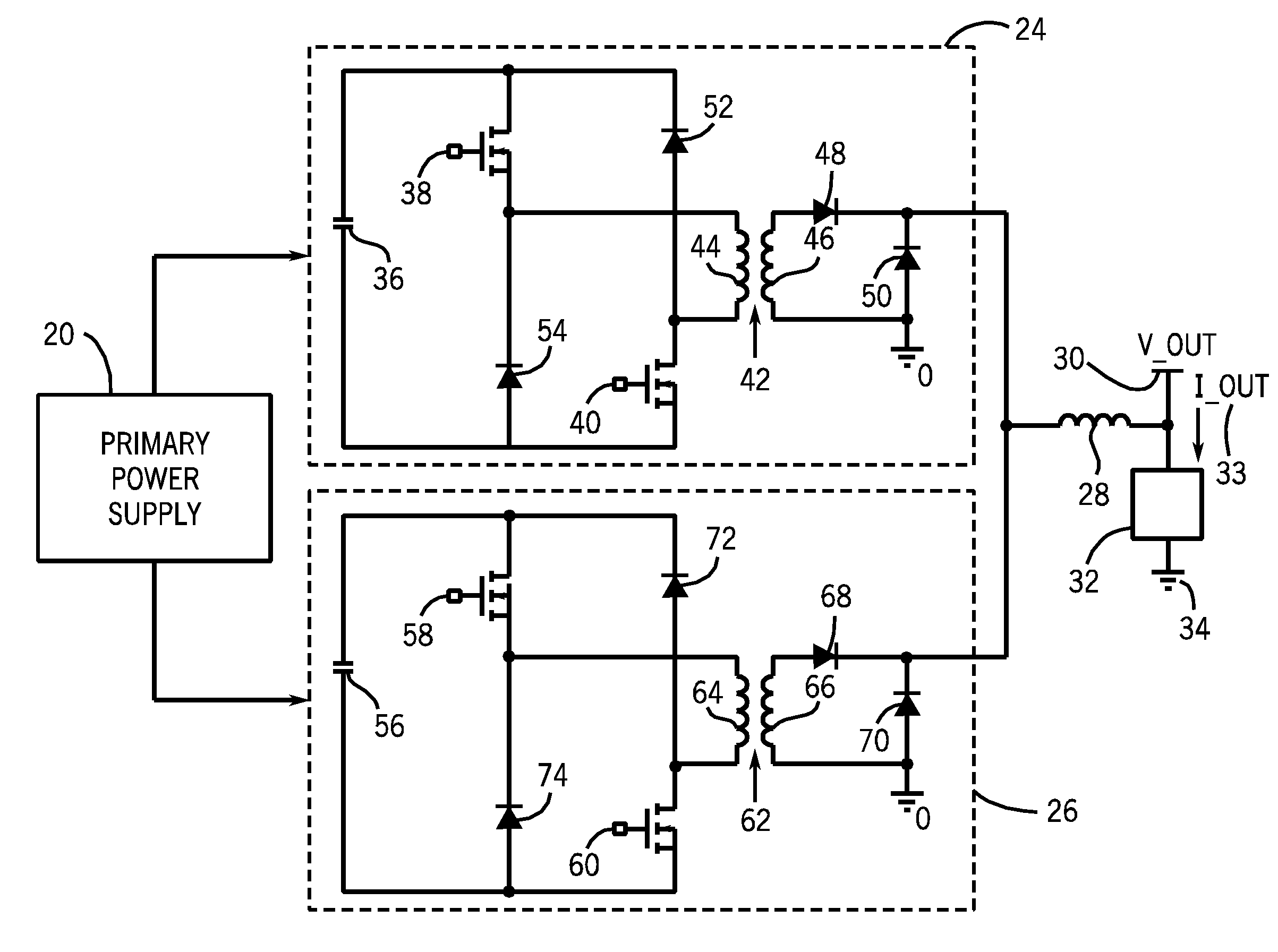
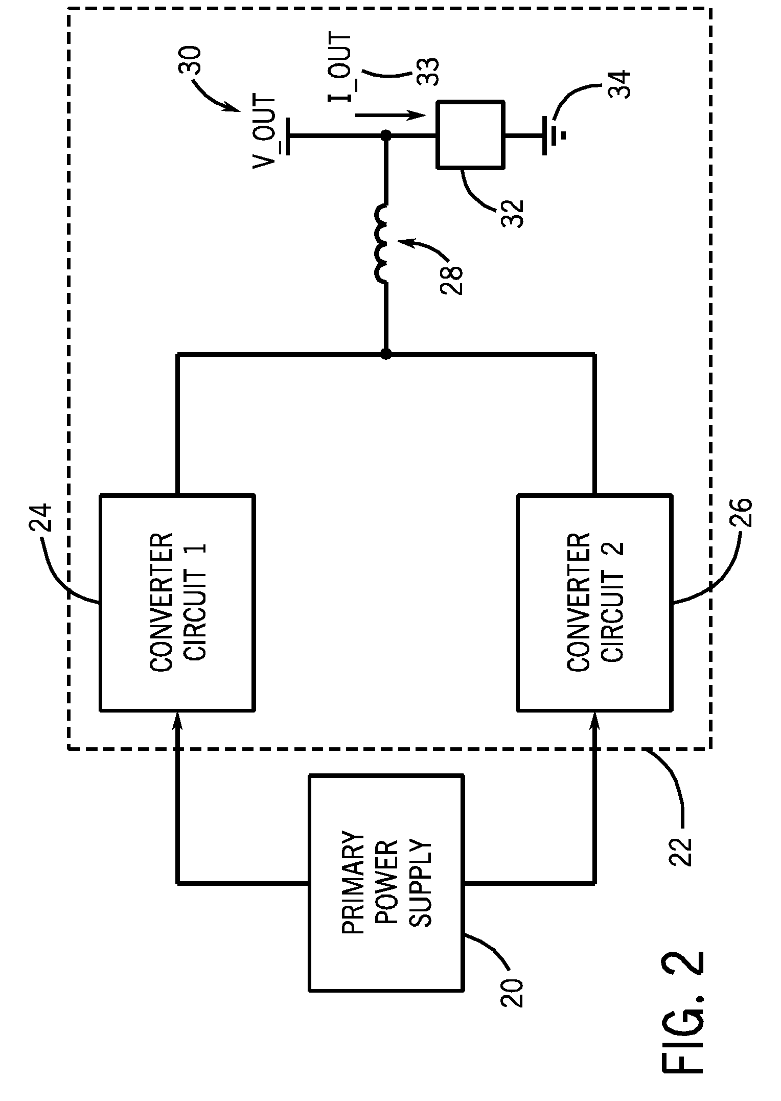
Welding or cutting power supply using phase shift double forward converter circuit (PSDF)
a converter circuit and power supply technology, applied in the direction of electric variable regulation, process and machine control, instruments, etc., can solve the problems of circuit with oversized components, inability to meet dynamic load voltage and current requirements, and lack of efficiency
- Summary
- Abstract
- Description
- Claims
- Application Information
AI Technical Summary
Benefits of technology
Problems solved by technology
Method used
Image

Examples
Embodiment Construction
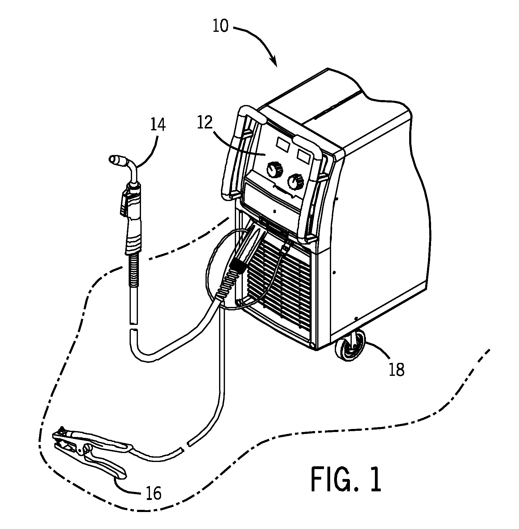
[0021]FIG. 1 illustrates an exemplary welding or plasma cutting power supply unit 10 which powers, controls, and provides supplies to a welding or cutting operation in accordance with aspects of the present invention. The side of the power supply unit 10 that faces the user contains a control panel 12, through which the user may control the supply of materials, such as power, gas flow, wire feed, and so forth, to a welding or cutting torch 14. A work lead clamp 16 typically connects to a workpiece to close the circuit between the torch 14, the work piece, and the supply unit 10, and to ensure proper current flow. It should be noted that in some embodiments, such as for stick welding operations, the torch 14 may be an electrode. The portability of the unit 10 depends on a set of wheels 18, which enable the user to move the power supply unit 10 to the location of the weld.
[0022]Internal components of the power supply unit 10 convert power from a wall outlet or other source of AC or DC...
PUM
| Property | Measurement | Unit |
|---|---|---|
| Temperature | aaaaa | aaaaa |
| Time | aaaaa | aaaaa |
| Current | aaaaa | aaaaa |
Abstract
Description
Claims
Application Information