Radiation diagram measuring system for a transmitting antenna

a technology of transmitting antenna and measuring system, which is applied in the direction of measuring interference from external sources, instruments, sensing by electromagnetic radiation, etc., can solve the problems of inability to provide data signals to the processing station, inability to ensure the proper positioning of the transmitting antenna, and relatively complicated mechanical structure of the receiving antenna. achieve the effect of simple and more precis

Inactive Publication Date: 2009-09-17
THE SWATCH GRP RES & DEVELONMENT LTD
View PDF11 Cites 36 Cited by
  • Summary
  • Abstract
  • Description
  • Claims
  • Application Information

AI Technical Summary

Benefits of technology

The invention is a system for measuring the radiation of a transmitting antenna. The goal is to provide a simpler and more accurate system for supplying data to a processing station. The current state of the art has limitations, and the invention aims to overcome them.

Problems solved by technology

The technical problem addressed in this patent is the need for a more accurate and efficient way to measure the radiation diagram of a transmitting antenna in electronic devices, without the need for a complicated mechanical structure to carry the receiving antenna.

Method used


Image

  • Radiation diagram measuring system for a transmitting antenna
  • Radiation diagram measuring system for a transmitting antenna
  • Radiation diagram measuring system for a transmitting antenna

Examples


Embodiment Construction

[0025]In the following description, all of the elements of the radiation diagram measuring system for a transmitting antenna, which are well known to those skilled in this technical field, will only be explained in a simplified manner.

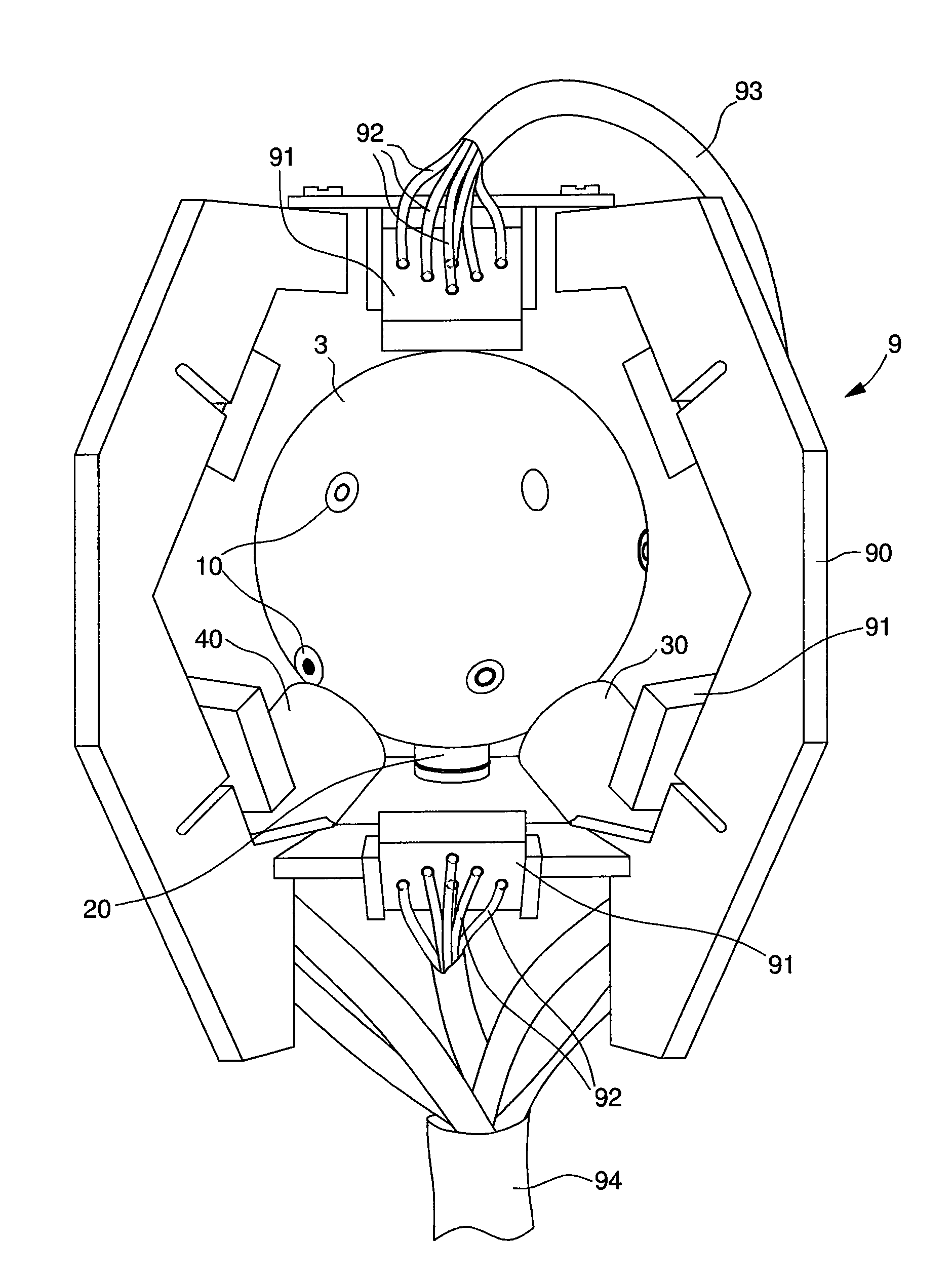
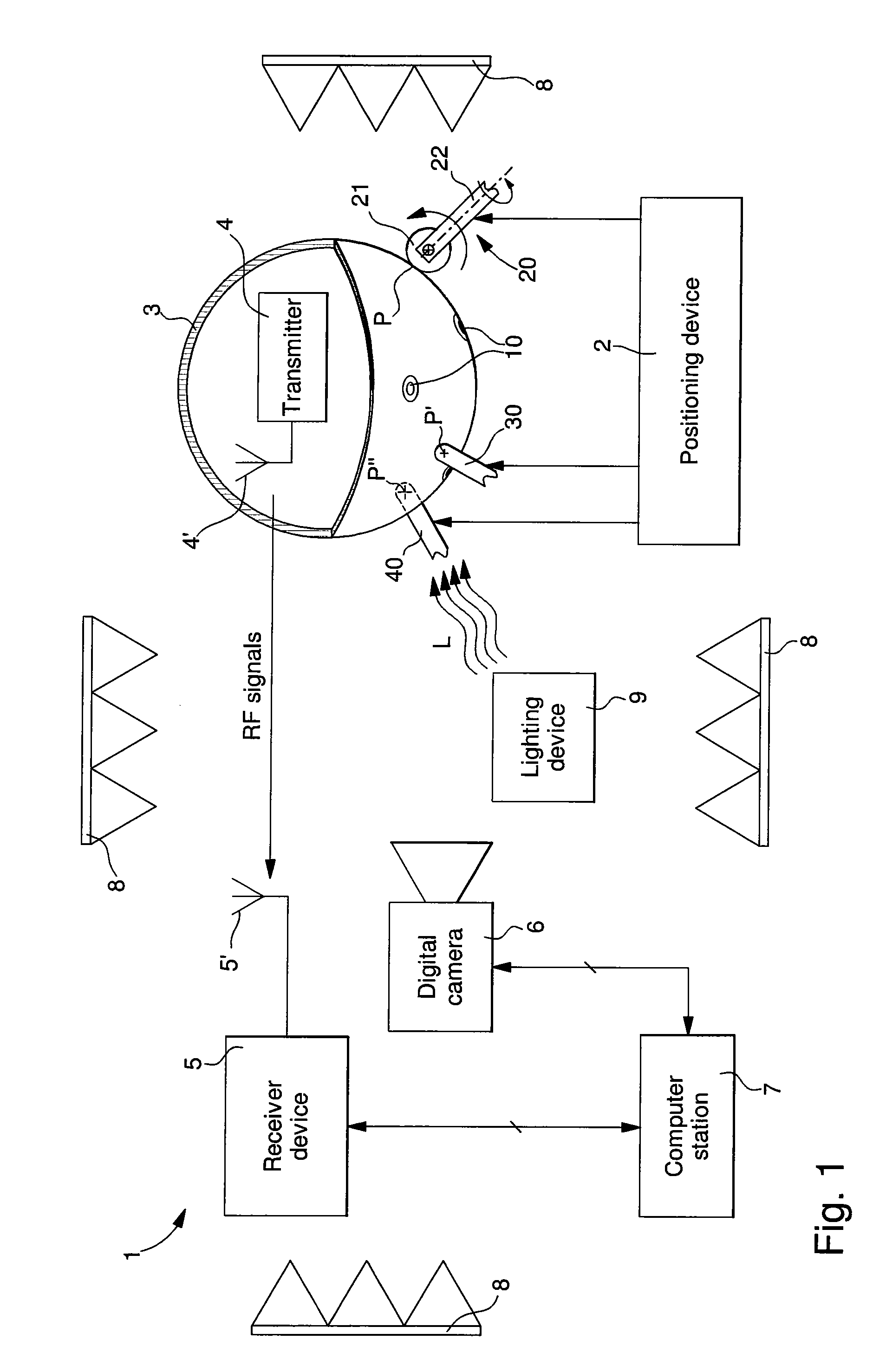
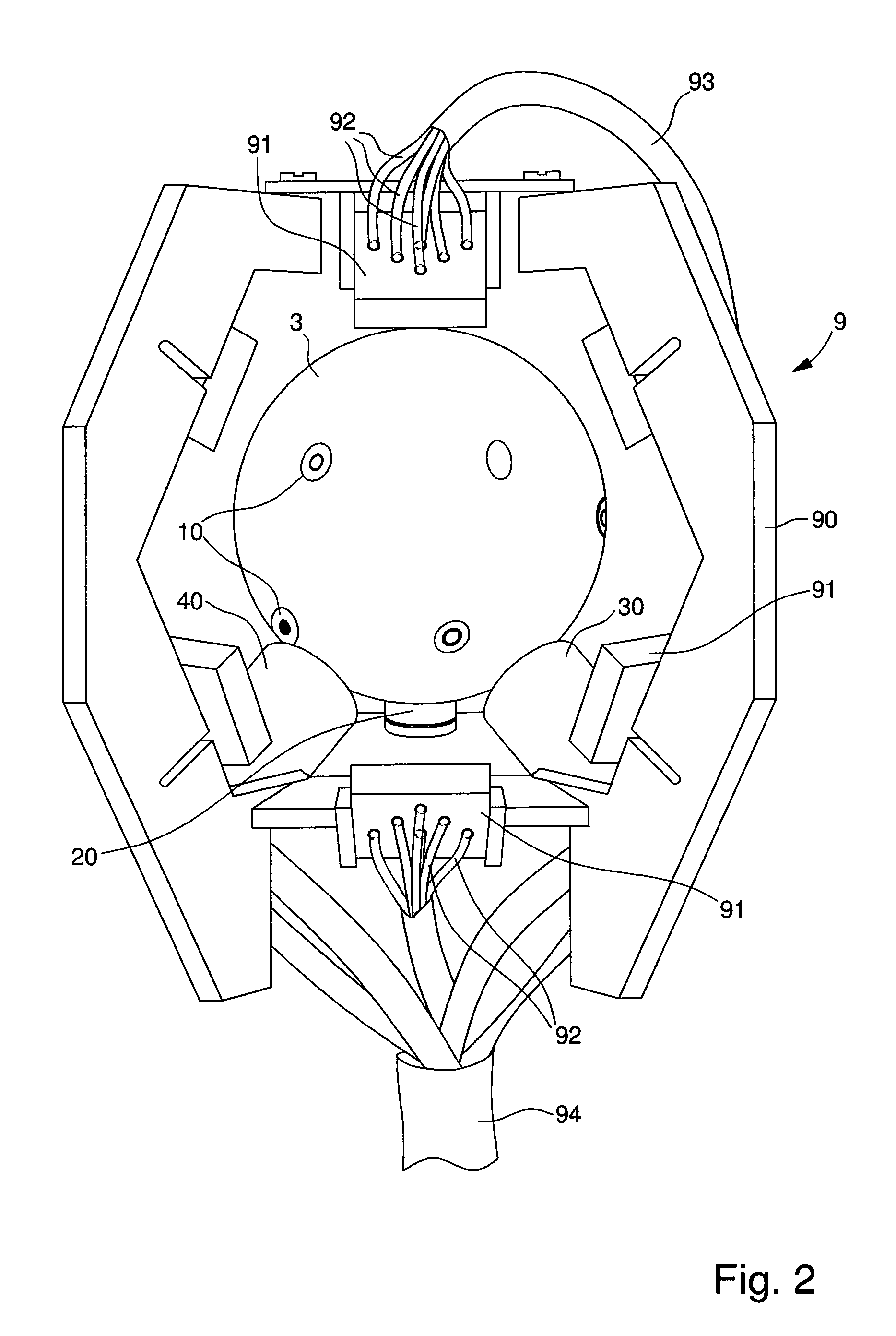
[0026]FIG. 1 illustrates schematically all of the elements of radiation diagram measuring system 1 for a transmitting antenna 4′ of an electronic transmitter device 4. Essentially, measuring system 1 includes, firstly, a positioning device 2, on which a spherical support element 3 for the electronic device is placed and held, by gravity, on three support points P, P“, P” of members 20, 30, 40. The electronic device with transmitting antenna 4′, which has to be measured, is held inside hollow sphere 3, which includes two parts, which fit on top of each other via any known means to close the electronic device. Transmitting antenna 4′ is preferably positioned close to the centre of the hollow sphere.

[0027]The measuring system further includes a receiver d...


PUM


Abstract

The measuring system includes a receiver including at least one fixed receiving antenna for picking up electromagnetic fields generated by a transmitting antenna belonging to an electronic device, and a positioning device on which a support element is placed. The positioning device includes mechanisms for driving the support element in rotation. The measuring system further includes a detection device for detecting position/orientation of the transmitting antenna, and a data processing station. A hollow spherical element houses the electronic device and is held on the positioning device by gravity on three points, one of which is formed by a drive member, and the two other points are formed using ball and socket joints. Several circular barcodes arranged on the external surface of the spherical element enable the system to determine the position/orientation of the spherical element using the digital camera.

Description


Claims


Application Information

Patent Timeline
Owner THE SWATCH GRP RES & DEVELONMENT LTD
Why Eureka
Try Eureka