Method and apparatus for rotating a component of a wind energy plant

a technology for wind energy plants and components, applied in the direction of propellers, dc motor stoppers, water acting propulsive elements, etc., can solve problems such as damage to components of wind energy plants

Active Publication Date: 2009-09-17
NORDEX ENERGY SE & CO KG
View PDF2 Cites 38 Cited by
  • Summary
  • Abstract
  • Description
  • Claims
  • Application Information

AI Technical Summary

Benefits of technology

[0013]According to the present invention, the driving torques are distributed differently to the at least two adjustment drives. In particular, the required total driving torque is essentially applied by one or more motive drives, wherein at least one drive acts against the desired rotational sense with a small counter-moment. Thus, a tightening of the drives against each other is realised. In this, the other rotational speed of the electric motor of one of the adjustment drives can be in particular an (absolutely) smaller rotational speed than the rotational speed of the other electric motor or the other electric motors, respectively, of the other adjustment drive or the other adjustment drives, respectively. However, another rotational speed can also mean that the absolute values of the rotational speeds are equal, but the rotational speeds have different signs. In this case, the electric motors are operated in different senses of rotation. Due to the difference of rotational speeds according to the present invention, a tightening of the drives against each other is achieved. In particular, the toothing of one gearbox of the adjustment drives contacts in the direction opposite to the sense of rotation. In this way, elasticities of the drives are minimised. According to the present invention, a sufficient tightening of the adjustment drives against each other is achieved in a manner which is simple with respect to construction and control technique as compared to the state of the art. In particular, this tightening is also existent in the traversing of the adjustment drives. Thus, in the load-dependent drive control with mutual tightening of the adjustment drives according to the present invention, at least one drive acts against the remaining adjustment drive or drives with its driving torque. A higher stiffness in the traversing of the adjustment devices is achieved. Moreover, in this way the moment-free ranges arising through the elasticities of the drives, the so-called torque holes, are reduced in starting and stopping processes. For instance, the acceleration which the machine house of the plant experiences when torque holes occur is damped correspondingly. In addition, accelerations caused by wind loads, which are greater than the driving torques, are avoided. Also, inadmissibly high rotational speeds of the adjustment systems are prevented, which would otherwise lead to a damage of components of the wind energy plant.
[0016]It is possible that the electric motors of the different adjustment drives are operated in opposite senses of rotation. But it is particularly preferred to operate the electric motors operated at different rotational speeds in the same sense of rotation. This embodiment is based on the finding that it is sufficient for an effective tightening of the drives when one of the drives is in fact operated in the same direction as the remaining drives, but with a smaller rotational speed. In this way, a sufficient tightening is achieved in a manner which is particularly gentle for the drives. By pre-setting such different desired rotational speeds in the triggering of the electric motors of the adjustment drives, one of the electric motors is quasi in a lag with respect to the remaining motors, and provides the tightening in this way. In particular, there is a slippage between the electric motors. In doing so, all the electric motors of all the adjustment drives can be operated in the same sense of rotation.
[0017]A moment regulation is preferably performed such that the respective adjustment drive(s) or electric motor(s), respectively, do not exceed a preset desired driving torque, and that adjustment drive or electric motor, respectively, which is operated at another rotational speed, a smaller one in particular, acts only with a fraction of the desired driving torque against the driving action of the remaining adjustment drive(s) or electric motor(s), respectively. Thus, the counter-acting torque cannot damage the adjustment drives and is in the permanently sustainable range of the gearbox. As a consequence, curtailings of the lifespan have not to be feared. According to one embodiment, in the traversing of the adjustment device, the adjustment drive featuring the electric motor operated at a different rotational speed can apply a torque directed against the driving torque of the at least one other adjustment drive of 5 to 10% of the driving torque of the at least one other adjustment drive. For instance, when each drive applies a rated moment of 100 Nm, the electric motor or adjustment drive, respectively, which is operated at the lower rotational speed, can apply a counter-moment of 5 to 10 Nm. According to a further embodiment, there can be a difference in rotational speed of 20 to 100 rotations per minute (rpm) between the electric motor operated at a different rotational speed, a lower one in particular, and the electric motor of the other adjustment drive or adjustment drives, respectively.
[0018]In principle, the present invention can be applied to all the adjustment devices in which there are elasticities and a tightening is therefore desirable. However, in a manner particularly suited for practice, the component can be a machine house of the wind energy plant and the adjustment device an azimuth adjustment device. Then, the machine house of the plant can be rotated around the longitudinal axis of the plant by the adjustment device. In this way it is possible for the rotor of the plant to follow the wind, and to untwist the cable loop between machine house and tower from time to time. But it is also possible that the component is a rotor blade of the wind energy plant, and the adjustment device a blade pitch angle adjustment device. In this case, the blade pitch angle of the rotor blades of the plant can be adjusted through the adjustment device by rotating the rotor blades around their longitudinal axis.
[0021]At high loads acting against the traversing movement of the adjustment device, the rotational speed of the at least one electric motor operated at a lower rotational speed can be increased. Thus, in this embodiment, at strong wind acting against the sense of rotation, the electric motor operated with the lower rotational speed, but in the same sense of rotation as the remaining electric motors, can also be operated at rated rotational speed, in order to support the remaining drives in the traversing of the adjustment device against the wind. Thus, the electric motor operated at lower rotational speed represents a power- and moment reserve which can be requested when needed. The total driving torque of the drives of the adjustment device is dimensioned such that all the drives together can safely traverse with maximum moment against the maximum occurring loads. The control device can feature a load measurement device, a wind measurement device for instance. When a limit load is exceeded, the control device can then increase the rotational speed of the braking electric motor which effects the tightening.
[0023]Due to the tightening of the adjustment drives in the manner of the present invention, it is furthermore possible that during the traversing of the adjustment device, no detent torque is exerted on the adjustment device by a braking device. Instead, this detent torque can be replaced by the tightening of the drives. As a consequence, the traversing of the adjustment device proceeds in a damped way, and a reduced wear and less necessity of maintenance result from this. In addition, the total driving torque to be applied by all the drives in common can be dimensioned smaller than when a detent torque is provided in the traversing. With a sufficient driving torque of the adjustment drives, even the braking device usually providing the detent torque (in the case of an azimuth adjustment device the brake disc and the brake calipers) can be omitted in principle. Admittedly, for starting and maintenance purposes, and also for the case of a grid breakdown, a device for arresting and holding, respectively, must be provided for the adjustment device. In this, those loads must be taken as a base which act on a wind energy plant which is in the spinning operation. Such a holding device has not to arrest rigidly when this is not demanded for safety reasons, but it may slip through when a limit load is exceeded. Inasmuch as the adjustment device features a conventional brake device nevertheless, the same can be kept unactuated during the traversing of the adjustment device, the brake calipers kept in the opened condition for instance.

Problems solved by technology

Also, inadmissibly high rotational speeds of the adjustment systems are prevented, which would otherwise lead to a damage of components of the wind energy plant.

Method used


Image

  • Method and apparatus for rotating a component of a wind energy plant
  • Method and apparatus for rotating a component of a wind energy plant
  • Method and apparatus for rotating a component of a wind energy plant

Examples


Embodiment Construction

[0031]While this invention may be embodied in many different forms, there are described in detail herein a specific preferred embodiment of the invention. This description is an exemplification of the principles of the invention and is not intended to limit the invention to the particular embodiment illustrated

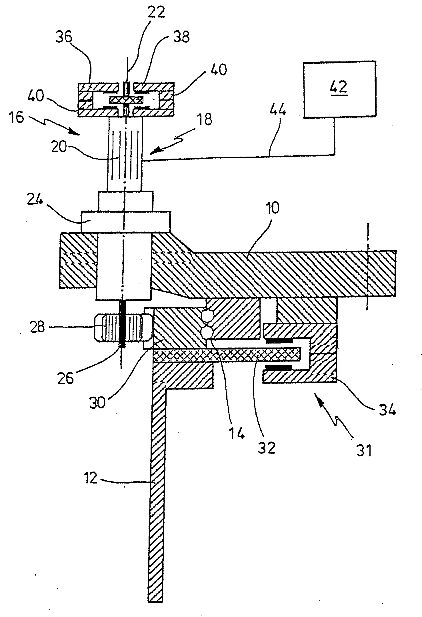
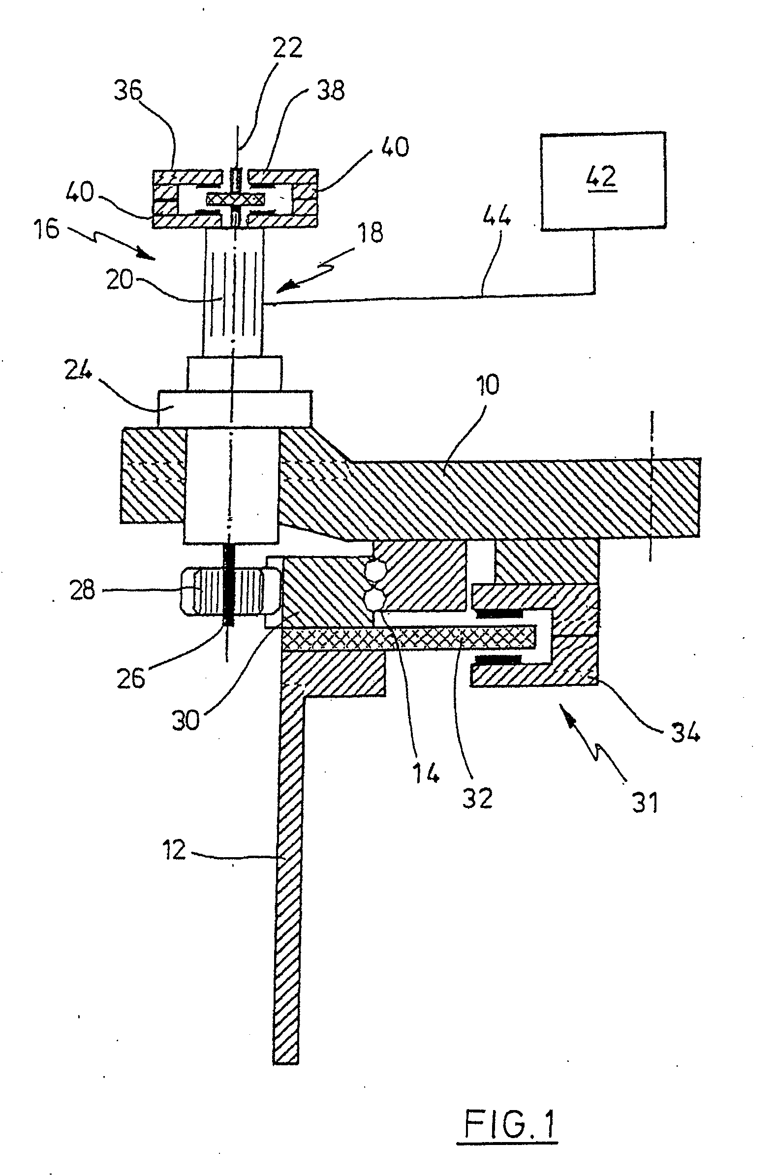
[0032]As far as not indicated otherwise, equal reference signs designate equal objects in the figures. In FIG. 1, an azimuth system of the wind energy plant with an adjustment device 16 according to the present invention is schematically shown, an azimuth adjustment device 16 in the depicted example. Of course, another adjustment system with another adjustment device, a blade pitch angle adjustment device for instance, could be provided as well. In the depicted example, the adjustment device 16 has three adjustment drives 18, presently azimuth adjustment drives 18, one of which can be recognised in FIG. 1. The adjustment device 16 serves for rotating a machine house of the win...


PUM


Abstract

The invention is related to a method for rotating a component of a wind energy plant by traversing an adjustment device, wherein the adjustment device comprises at least two adjustment drives, each one thereof having at least one electric motor, for traversing the adjustment device, and wherein during the traversing of the adjustment device, the electric motor of at least one of the at least two adjustment drives is operated at another rotational speed than the electric motor of at least one other of the at least two adjustment drives. Furthermore, the invention is related to a corresponding device.

Description

CROSS-REFERENCE TO RELATED APPLICATIONS[0001]Not applicable.STATEMENT REGARDING FEDERALLY SPONSORED RESEARCH[0002]Not applicable.BACKGROUND OF THE INVENTION[0003]The present invention is related to a method and an apparatus for rotating a component of a wind energy plant by traversing an adjustment device. Adjustment devices are used in wind energy plants for rotating various components. A known example is the blade pitch angle adjustment device, by which the blade pitch angle of the rotor blades of the plant is adjusted. By doing so, the rotor blades are rotated around their longitudinal axes. Such a blade pitch angle adjustment device is usually a part of a so-called pitch regulation. Another also known example are azimuth adjustment devices, by which the machine house of the wind energy plant is rotated around the longitudinal axis of the tower. Such azimuth adjustment devices form a part of a so-called azimuth system of the wind energy plant, which has the objective to orient th...

Claims


Application Information

Patent Timeline
Patent Type & Authority Applications(United States)
IPC IPC(8): F03D7/00H02P3/14
CPCF03D7/0204F03D7/0224F05B2240/40Y02E10/723F05B2270/602Y02E10/721F05B2260/90Y02E10/72
Inventor KELLER, HARALDWIESE-MULLER, LARS-ULRICHVOSS, EBERHARD
Owner NORDEX ENERGY SE & CO KG
Why Eureka
Try Eureka