Cooling system by contact

Inactive Publication Date: 2009-09-24
PRENDAS CAPRICORNIO SL
View PDF20 Cites 7 Cited by
  • Summary
  • Abstract
  • Description
  • Claims
  • Application Information

AI Technical Summary

Benefits of technology

[0043]Optionally, the system is housed inside a therm

Problems solved by technology

Said devices present the drawback that they include at said garment a very extended and complex tubing circuit through which the cooling substance flows, resulting in a not very flexible garment.
Furthermore, the tubes cool the garment only when the pressurized gas flows through them, but they cannot store frigories (negative calories) during a long time.
In the other hand, any torn of said garment can affect the circuit, making the cooling device useless, and it can also promote a leak of said coolant which, depending on the kind of substance used, can involve a serious danger for the user of the device.
Furthermore, another drawba

Method used


Image

  • Cooling system by contact
  • Cooling system by contact
  • Cooling system by contact

Examples


first embodiment

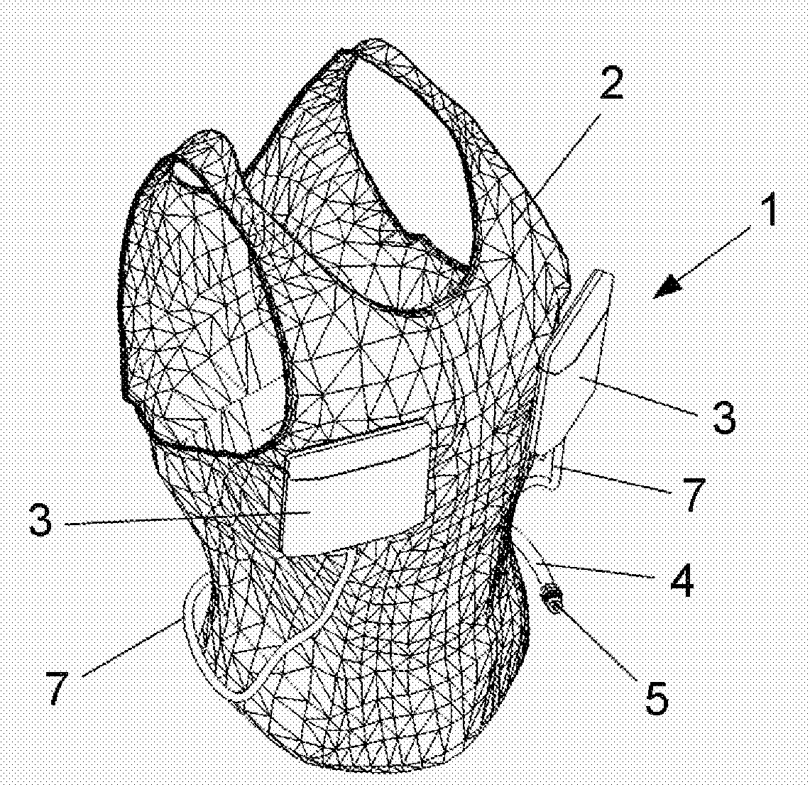
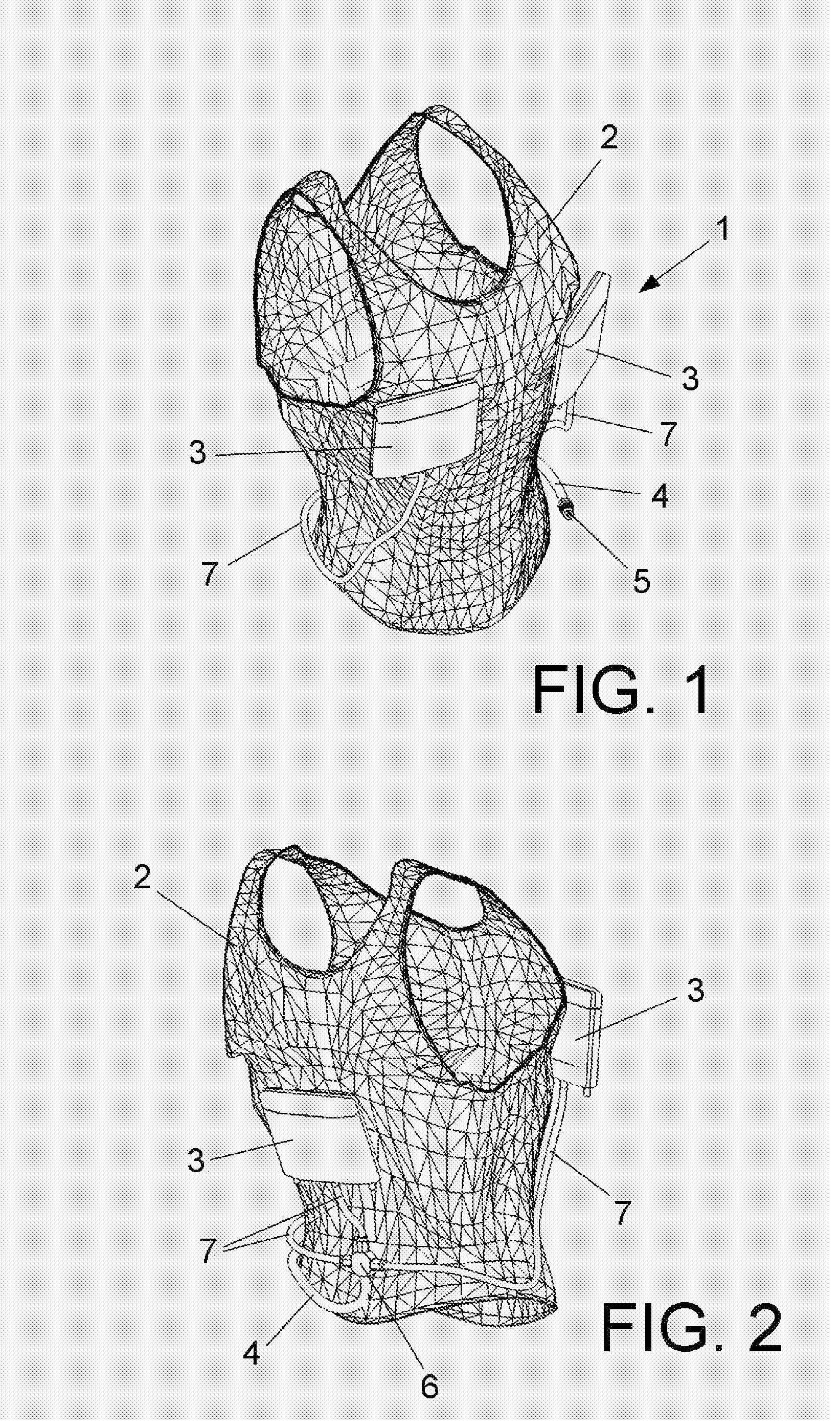
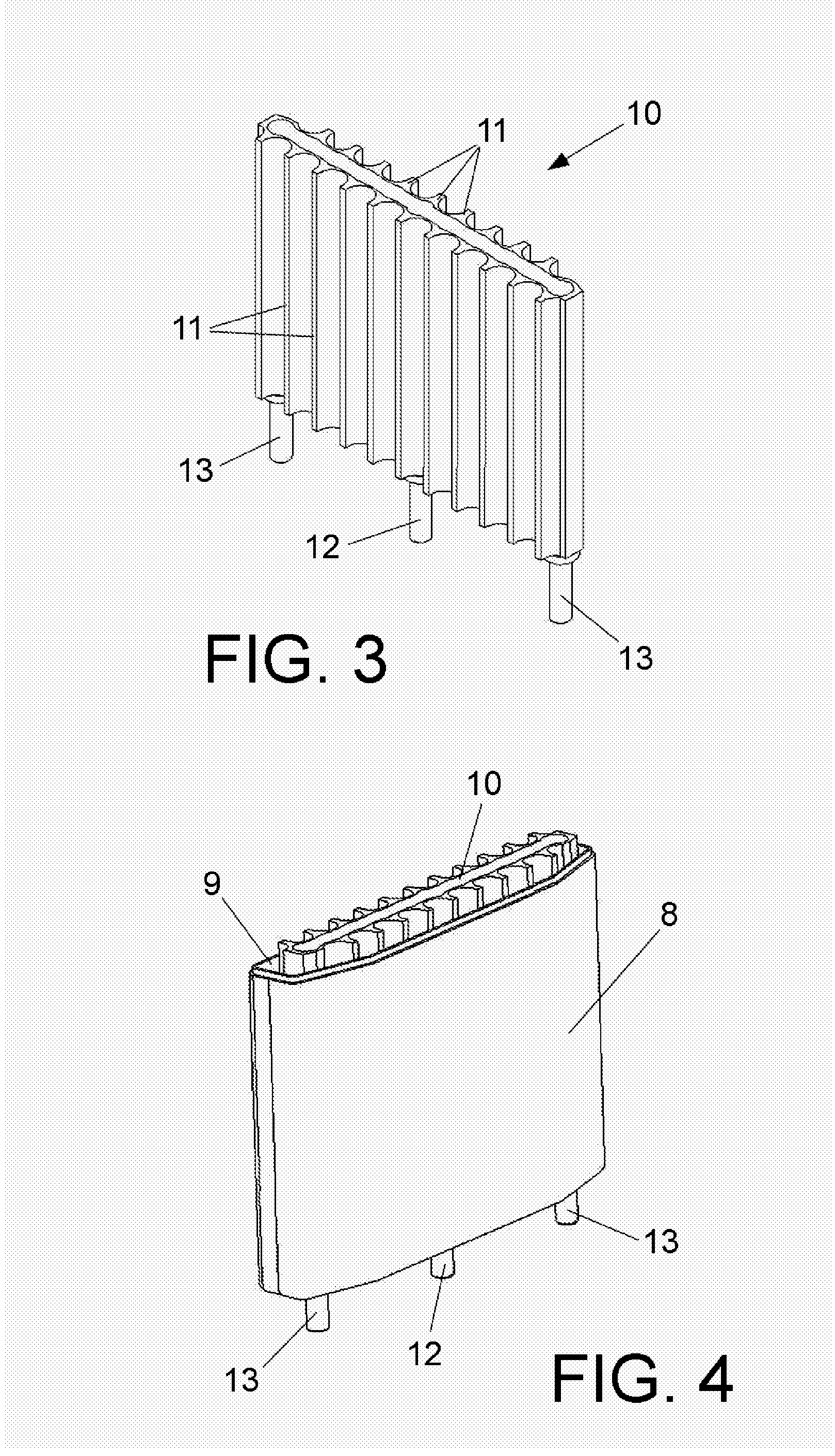
[0023]According to the invention, the system is engaged on a garment. Advantageously, said at least one device for collecting and storing frigories comprises a thermally isolated container, with the exception of a cold transmission surface in direct or indirect contact with the body or object to be cooled.

[0024]Preferably, the container comprises a radiator provided with internal channels and external wings.

[0025]Advantageously, the container also comprises a viscous gel around the radiator, filling the volume of the container not occupied by the radiator.

second embodiment

[0026]According to the invention, the system is engaged inside a protection helmet between an external layer and a cold transmission surface in contact with the head of the user.

[0027]Advantageously, said at least one device for collecting and storing frigories comprises a tube for conducting and distributing cooling fluid, preferably in spiral shape, occupying the whole extension of the helmet.

[0028]Preferably, the tube for conducting and distributing cooling fluid is placed inside a security padded layer.

[0029]Advantageously, said at least one device for collecting and storing frigories also comprises a layer of viscous gel placed between the tube for conducting and distributing cooling fluid and the cold transmission surface.

third embodiment

[0030]According to the invention, the system is engaged to a fridge or cold recipient.

[0031]Advantageously, said at least one device for collecting and storing frigories comprises a container thermally isolated by an external isolating layer, with the exception of a cold transmission surface in direct or indirect contact with the internal part of the fridge.

[0032]Preferably, the container comprises a viscous gel.

[0033]Advantageously, the cooling fluid is a cryogenic fluid. Preferably, said cryogenic fluid is liquid nitrogen.

[0034]In anyone of the previous embodiments, the system comprises means for conducting and distributing said cooling fluid to said at least one device for collecting and storing frigories or, in other words, absorbing heat.

[0035]Advantageously, said means for conducting and distributing the cooling fluid include an intake duct provided at an end with an intake nozzle provided with a valve to be connected intermittently to the external charging device.

[0036]Prefer...


PUM


Abstract

A cooling system which comprises a cooling fluid to cool a body or object, and at least a cold transmission surface in direct or indirect contact with said body or object. It is characterized in that it comprises at least a device for collecting and storing frigories that can receive a preset quantity of cooling fluid from an external charging device, store said frigories and transmit them at a preset velocity and temperature to said cold transmission surface. It is obtained a system in which it is not necessary to use a cryogenic deposit forming part of it, so that the security is enhanced and the cost is reduced. Further, the invention comprises a device (3) for absorbing heat that comprises a thermally isolated container (8), with the exception of a cold transmission surface (9) in direct or indirect contact with the body or object to be cooled, said container (8) comprising a radiator (10) that can receive a preset quantity of said cryogenic cooling fluid from an external charging device, and in that said container (8) also comprises a material around the radiator (10), filling the volume of the container (8) not occupied by the radiator (10), said material having a thermal conductivity suitable of storing the negative calories (frigories) transferred by contact from said radiator (10), and for transmitting said negative calories (frigories) at a preset velocity and preset temperature to said cold transmission surface (9). Furthermore, the system provides a great autonomy because it can store a great quantity of frigories.

Description

CROSS-REFERENCE TO RELATED APPLICATION[0001]This application is the U.S. national phase of PCT / EP2007 / 054466, filed May 9, 2007. PCT / EP2007 / 054466 claims benefit under the Paris Convention to ES P-200601192, filed May 10, 2006. The disclosures of both of ES P-200601192 and PCT / EP2007 / 054466 are hereby incorporated herein by reference.SUMMARY OF THE INVENTION[0002]The present invention refers to a cooling system by contact.BACKGROUND OF THE INVENTION[0003]There are known different cooling systems by contact of a body or object, as will be described hereinafter.[0004]U.S. Pat. No. 5,438,707 and U.S. Pat. No. 4,738,119 disclose, respectively, cooling devices of a body comprising a garment which houses a tubing network provided with little openings or micropores through which pressurized gas flows, such as air or carbon dioxide. Said pressurized gas, once injected, expands quickly through said openings or micropores cooling itself and absorbing a great quantity of heat, producing a cool...

Claims


Application Information

Patent Timeline
IPC IPC(8): A41D13/005
CPCA41D13/0053A42B3/285A61F7/10F25D2400/26A61F2007/0018A61F2007/0056A62B17/005A61F2007/0002A42B3/28
Inventor SERRANO MOLINA, JOSE ANTONIO
Owner PRENDAS CAPRICORNIO SL
Why Eureka
Try Eureka