
Optical axis orientation measuring device, optical axis orientation measuring method, spherical surface wave device manufacturing device, and spherical surface wave device manufacturing method

a technology of optical axis and measuring device, which is applied in the direction of optical axis determination, optical radiation measurement, instruments, etc., can solve the problems of complex type of operation and inaccuracy of position, and achieve the effect of easy measurement of the optical axis

Inactive Publication Date: 2009-09-24
YAMATAKE HONEYWELL CO LTD
View PDF2 Cites 2 Cited by
  • Summary
  • Abstract
  • Description
  • Claims
  • Application Information

AI Technical Summary

Benefits of technology

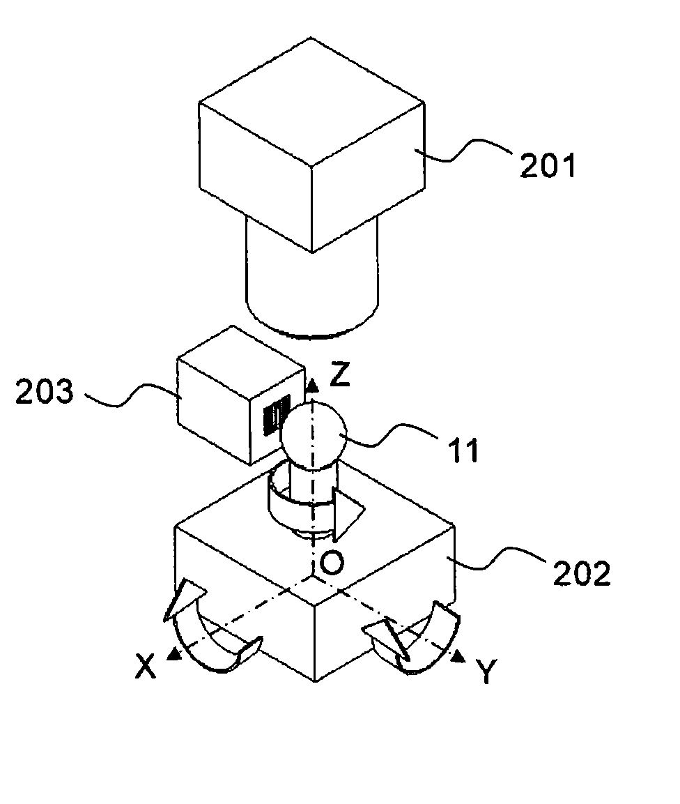
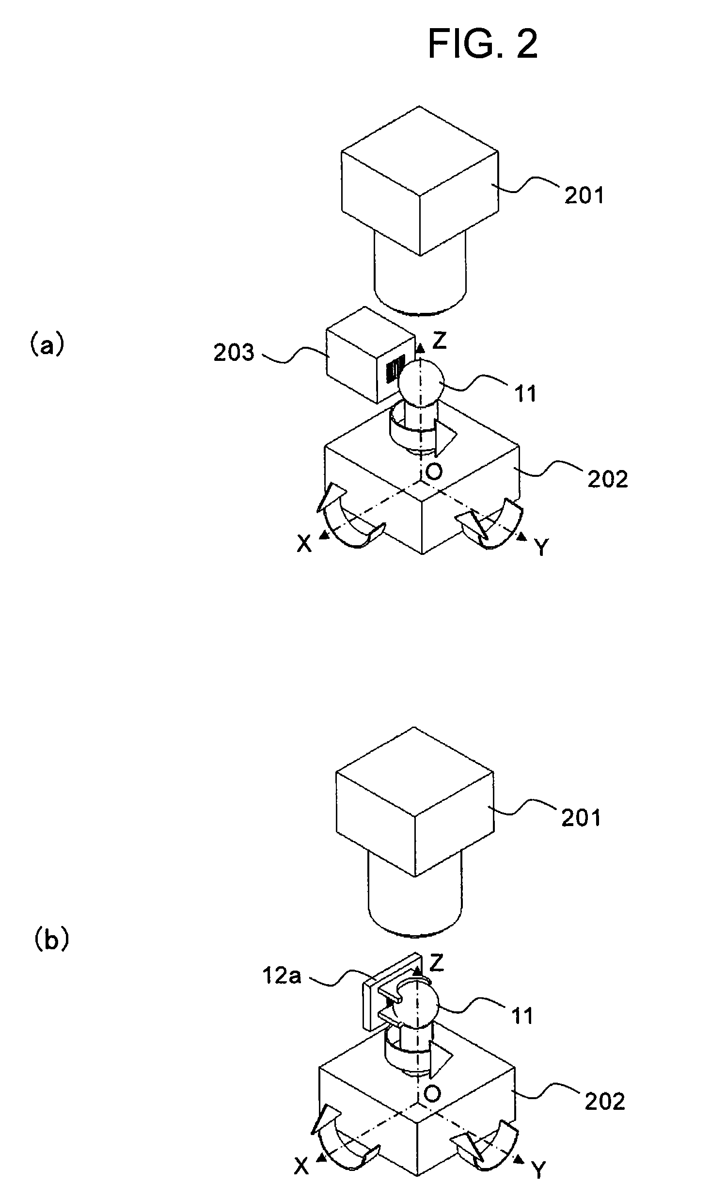
The present invention provides an optical axis orientation measuring device and method for a spherical member made from a single crystal of an optically uniaxial crystal having birefringence. The device includes an illuminating means for illuminating the spherical member through a polarizer and an isogyre observing means for observing the isogyre that is structured by the light reflected from the bottom surface of the spherical member and emitted from the spherical member through an analyzer that has a cross-nicol relationship with the polarizer. The device also includes supporting means for supporting the spherical member from the side opposite from that whereon the light is incident. The method includes the steps of causing light to be incident on the spherical member through a polarizer and observing the isogyre that is structured by the light reflected from the bottom surface of the spherical member and emitted from the spherical member through an analyzer that has a cross-nicol relationship with the polarizer. The device and method make it easy to measure the optical axis of a spherical optically uniaxial crystal and detect the equatorial plane.

Problems solved by technology

This type of operation is complex, and there is the possibility that, in this process, there will be inaccuracies in the position at which the comb electrode 12 is formed.
Consequently, after the measurement of the optical axis, it is not possible to determine the optimal position for forming the comb electrode 12 by exciting a surface acoustic wave from the outside while in that state, leaving no choice but to transfer to the next process.

Method used


Image

  • Optical axis orientation measuring device, optical axis orientation measuring method, spherical surface wave device manufacturing device, and spherical surface wave device manufacturing method
  • Optical axis orientation measuring device, optical axis orientation measuring method, spherical surface wave device manufacturing device, and spherical surface wave device manufacturing method
  • Optical axis orientation measuring device, optical axis orientation measuring method, spherical surface wave device manufacturing device, and spherical surface wave device manufacturing method

Examples


Embodiment Construction

[0026]A form of embodiment of the present invention will be described below. Note, however, that the present invention is not limited to the form of embodiment set forth below. Additionally, for clarity in the explanation, the description and drawings below have been abbreviated and simplified as appropriate.

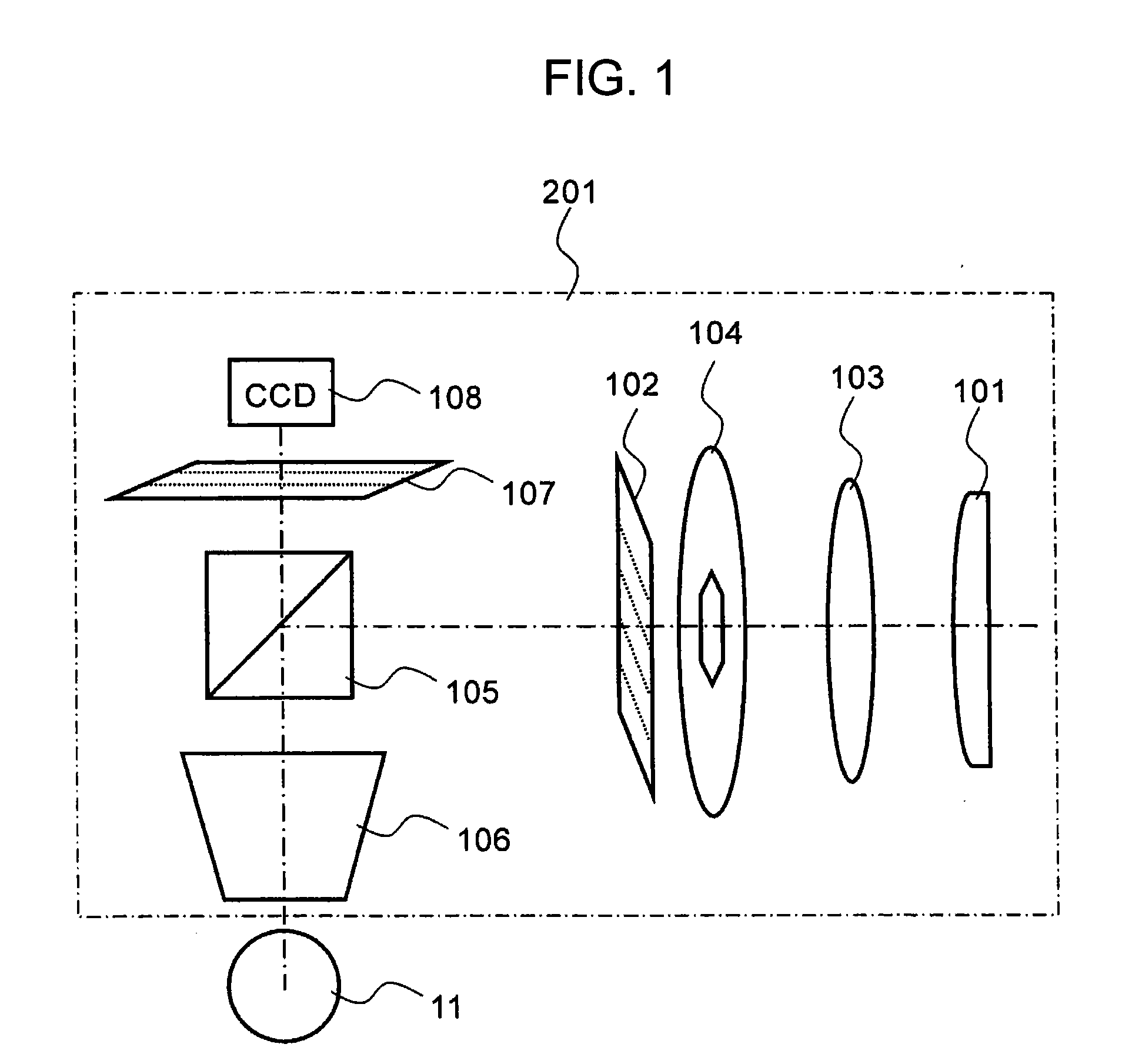
[0027]The optical axis orientation measuring device for a spherical member made out of an optically uniaxial single crystal according to the present form of embodiment of the present invention will be explained using FIG. 1. The optics system for measurement will be explained first. FIG. 1 is a diagram illustrating schematically the structure of the optics system for measurement in relation to the present form of embodiment. The optics system for measurement in relation to the present form of embodiment is provided with a light source 101, a polarizer 102, a light wavelength filter 103, an aperture stop 104, a half mirror 105, an object lens 106, an analyzer 107, and a CCD camer...


PUM


Abstract

The optical axis orientation measuring device according to the present invention is a reflective optical axis orientation measuring device for a spherical member made from a single crystal of an optically uniaxial crystal having birefringence, comprising: illuminating means for illuminating the spherical member through a polarizer; and isogyre observing means for observing the isogyre that is structured by the light that is reflected from the bottom surface of the spherical member and emitted from the spherical member through an analyzer that has a cross-nicol relationship with the polarizer.

Description

CROSS REFERENCE TO PRIOR APPLICATIONS[0001]The present application claims priority under U.S.C. §119 to Japanese Patent Application No. 2008-075864, filed Mar. 24, 2008. The content of the application is incorporated herein by reference in its entirety.FIELD OF TECHNOLOGY[0002]The present invention relates to an optical axis orientation measuring method, an optical axis orientation measuring device using said method, a spherical surface acoustic wave device manufacturing method, and a spherical surface acoustic wave device manufacturing device using said method.BACKGROUND OF THE INVENTION[0003]There is a ball SAW sensor (spherical Surface Acoustic Wave device) that uses the change in the propagation speed depending on the ambient hydrogen concentration when a surface acoustic wave (SAW) propagates on the surface of a sphere made from a single crystal piezoelectric material such as liquid crystal, langasite, LiNbO3, LiTaO3, or the like. (See Japanese Unexamined Patent Application Pub...

Claims


Application Information

Patent Timeline
Patent Type & Authority Applications(United States)
IPC IPC(8): H04R29/00G01M11/02
CPCG01M11/0221
Inventor EBI, YUSUKESEGAWA, SUSUMU
Owner YAMATAKE HONEYWELL CO LTD
Learn More