Ventilating device for fuel tank

a technology for fuel tanks and ventilators, which is applied in the direction of valves, functional valve types, operating means/releasing devices, etc., can solve the problems of complicated and elongated piping arrangements, light leakage, and complicated design, and achieves simple design, inhibits outflow of fuel, and is easy to produce

Inactive Publication Date: 2009-09-24
TOYODA GOSEI CO LTD
View PDF0 Cites 34 Cited by
  • Summary
  • Abstract
  • Description
  • Claims
  • Application Information

AI Technical Summary

Benefits of technology

[0052]The embodiment described above affords the following effects and advantages.
[0053](6)-1 Even where the vehicle has a full tank and has assumed a condition tilted as far as either the first or second maximum tilt angle, in the fuel tank ventilating device, either the first fuel cutoff valve 20 or the second fuel cutoff valve 40 will open so that venting of the fuel tank FT to the outside can be assured.
[0054](6)-2 As the means for preventing outflow of fuel to the canister CS through the second flow pipe CP2 in the second submersion state with the second fuel cutoff valve 40 submerged as depicted in FIG. 8, the connecting part CP-J is disposed at a location whereby the second flow pipe CP2 is longer than the first flow pipe CP1, rather than the first flow pipe CP1 and the second flow pipe CP2 being of equal length. With this arrangement, even if the first flow pipe CP1 and the second flow pipe CP2 are routed on the horizontal, if the fuel tank FT should tilt, to the extent that the second flow pipe CP2 is longer it will be easier for the connecting part CP-J to be positioned above the fuel level in the fuel tank FT, that is, it will be easier to produce a pipe arrangement that inhibits outflow of fuel to the canister CS. Consequently, there will be no need for a complicated and elongated line or a line having a section which has been made higher through a bending process as described in the prior art, thus affording a simpler design.
[0055](6)-3 An arrangement whereby the connecting part CP-J is disposed at a location such that the first flow pipe CP1 is shorter than the second flow pipe CP2 will, owing to the shorter length of the first flow pipe CP1, make it more difficult for the connecting part CP-J to be situated at a high position when the fuel tank FT is tilted; and will make it easie

Problems solved by technology

Despite enhanced sealing ability provided by a valve body of rubber or the like, the fuel cutoff valve in the closed state will not be able to prevent outflow of fuel to the canister, and slight leakage will occu

Method used


Image

  • Ventilating device for fuel tank
  • Ventilating device for fuel tank
  • Ventilating device for fuel tank

Examples


Embodiment Construction

(1) Overall Configuration of Fuel Tank Ventilating Device

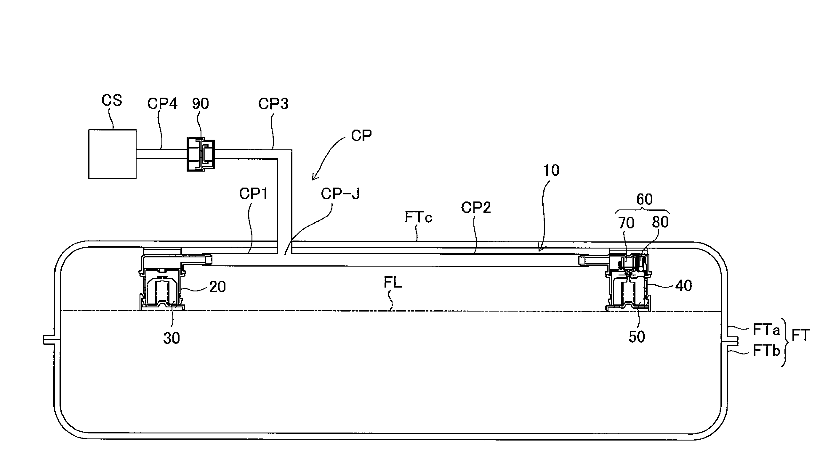
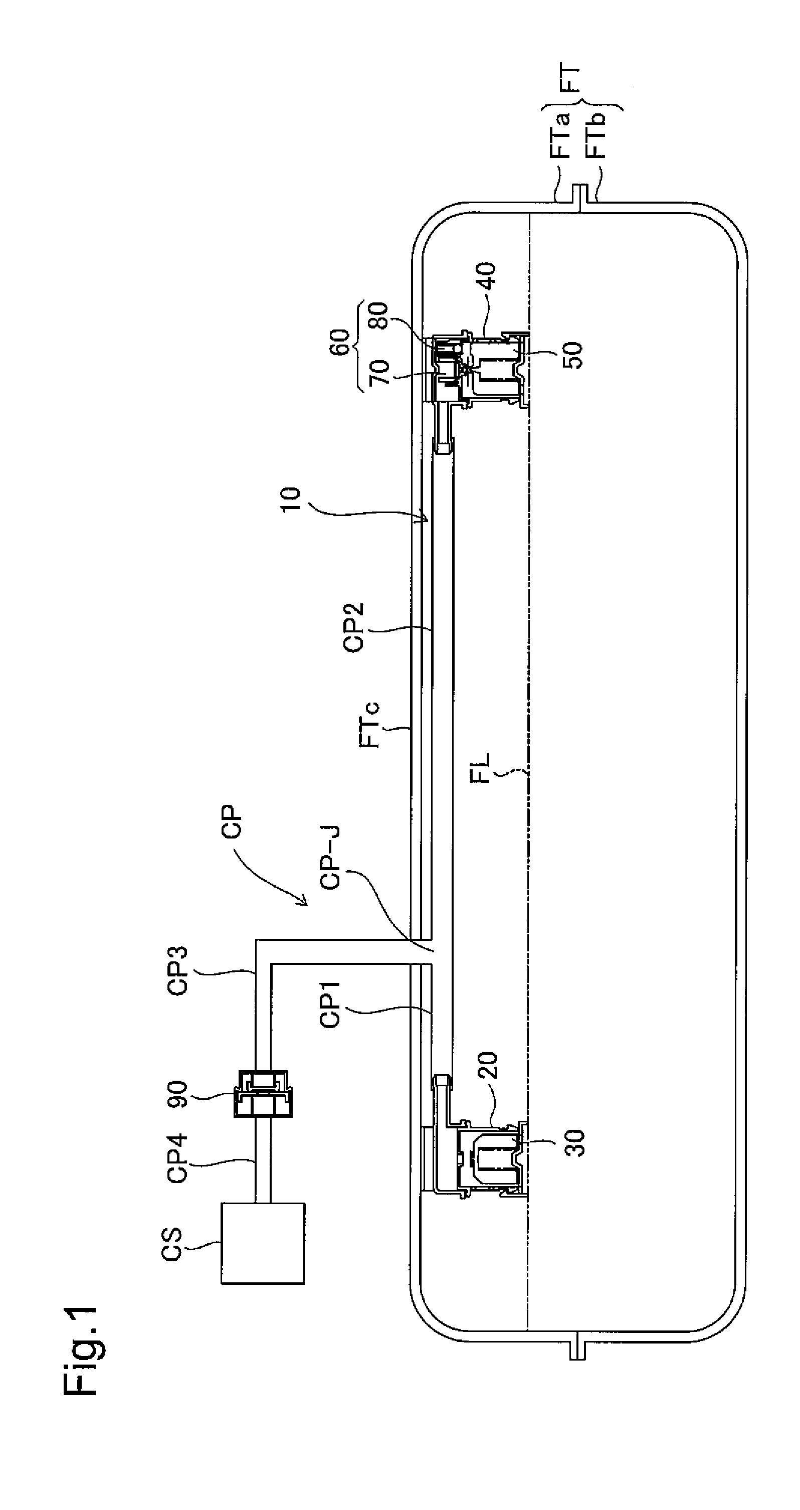
[0023]FIG. 1 is an illustration depicting a fuel tank FT having an installed fuel tank ventilation device according to an embodiment of the present invention. The fuel tank FT is a flattened tank adapted to ensure a roomy passenger cabin in the vehicle, and is formed split into two parts, an upper half part FTa and a lower half part FTb which are joined together. The fuel tank ventilation device is disposed on the lower wall FTc and to the upper of the fuel tank FT. The fuel tank ventilation device has a fuel cutoff device 10; a connecting pipe CP that connects the fuel cutoff device 10 to a canister CN; and a positive / negative pressure valve 90. The fuel cutoff device 10 also includes a first fuel cutoff valve 20 and a second fuel cutoff valve 40 respectively situated to either side of the upper section of the fuel tank FT. The first fuel cutoff valve 20 and the second fuel cutoff valve 40 ensure venting of the fuel tank FT t...


PUM


Abstract

The fuel tank ventilating device includes a fuel cutoff device, and a connector pipe connecting the fuel cutoff device with a canister. The fuel cutoff device includes a first fuel cutoff valve, a second fuel cutoff valve, and a positive pressure valve; the first flow pipe and the second flow pipe are connected to a third flow pipe by a connecting part, and are connected to the canister. With the first fuel cutoff valve in a first submersion state, fuel that has collected in the first flow pipe will be returned to the fuel tank on the basis of a differential pressure between tank internal pressure and the pipe internal pressure bearing on the fuel inside the first flow pipe. With the first fuel cutoff valve in a submersion state, fuel that has leaked into the second flow pipe will not reach the connecting part.

Description

[0001]This application claims the benefit of and priority from Japanese Application No. 2008-71046 filed Mar. 19, 2008, the content of which is incorporated herein by reference.BACKGROUND OF THE INVENTION[0002]1. Field of the Invention[0003]The present invention relates to a ventilating device for a fuel tank, adapted to prevent fuel from spilling from the fuel tank to the outside.[0004]2. Description of the Related Art[0005]One known technology proposed for a fuel tank ventilating device of this kind is that disclosed in JP-A 2005-172161, for example. Specifically, the fuel tank ventilating device is provided with a fuel cutoff valve (rollover valve) and a full tank regulating valve connected to a canister, these being disposed in the upper part of the fuel tank; through appropriate opening and closing of the valves at prescribed fuel levels, venting of the fuel tank to the outside may be assured while at the same time preventing the liquid fuel from spilling to the outside. Despit...

Claims


Application Information

Patent Timeline
IPC IPC(8): B65D90/22F16K31/18B60K15/035
CPCB60K15/03504F16K24/044F16K17/196B60K15/03519Y10T137/0874Y10T137/7358
Inventor MIURA, NATSUSHI
Owner TOYODA GOSEI CO LTD
Why Eureka
Try Eureka