LED assembly with separated thermal and electrical structures thereof

Inactive Publication Date: 2009-09-24
HON HAI PRECISION IND CO LTD
View PDF6 Cites 42 Cited by
  • Summary
  • Abstract
  • Description
  • Claims
  • Application Information

AI Technical Summary

Benefits of technology

[0008]An LED assembly includes a substrate and a plurality of LEDs mounted on the substrate. Each LED comprises an LED die, a base supporting the LED die thereon and thermally contacting the substrate to transfer heat generated by the LED die to the substrate, a pair of leads electrically connecting the LED die to supply a current to the LED die, and an encapsulant enveloping the LED die therein. The pair of leads extends above the substrate so that an electrical route of the LED assembly is separated from a he

Problems solved by technology

However, when the LED is in operation, it generates a great deal of heat, which may result in the LED overheating or even malfunction if the heat cannot be dissipated timely.
Nonetheless, there is a problem in this type of LED assembly: since both of the current flux and the heat flux are transferred via the anode and the cathode portions and the substrate, a current transferring pathway of the LED assembly substantially overlaps a heat conducting pathway thereof; thus, the current is easily influenced by the heat.
As the temperature of the anode and

Method used


Image

  • LED assembly with separated thermal and electrical structures thereof
  • LED assembly with separated thermal and electrical structures thereof
  • LED assembly with separated thermal and electrical structures thereof

Examples


first embodiment

[0035]Referring to FIGS. 1 and 8, an LED assembly in accordance with the present invention comprises a substrate 10 and an LED unit 200 mounted on the substrate 10.

[0036]The substrate 10 is solid and entirely made of metal, such as copper, aluminum or an alloy thereof. The substrate 10 has a large and flat top surface for mounting the LED unit 200 thereon.

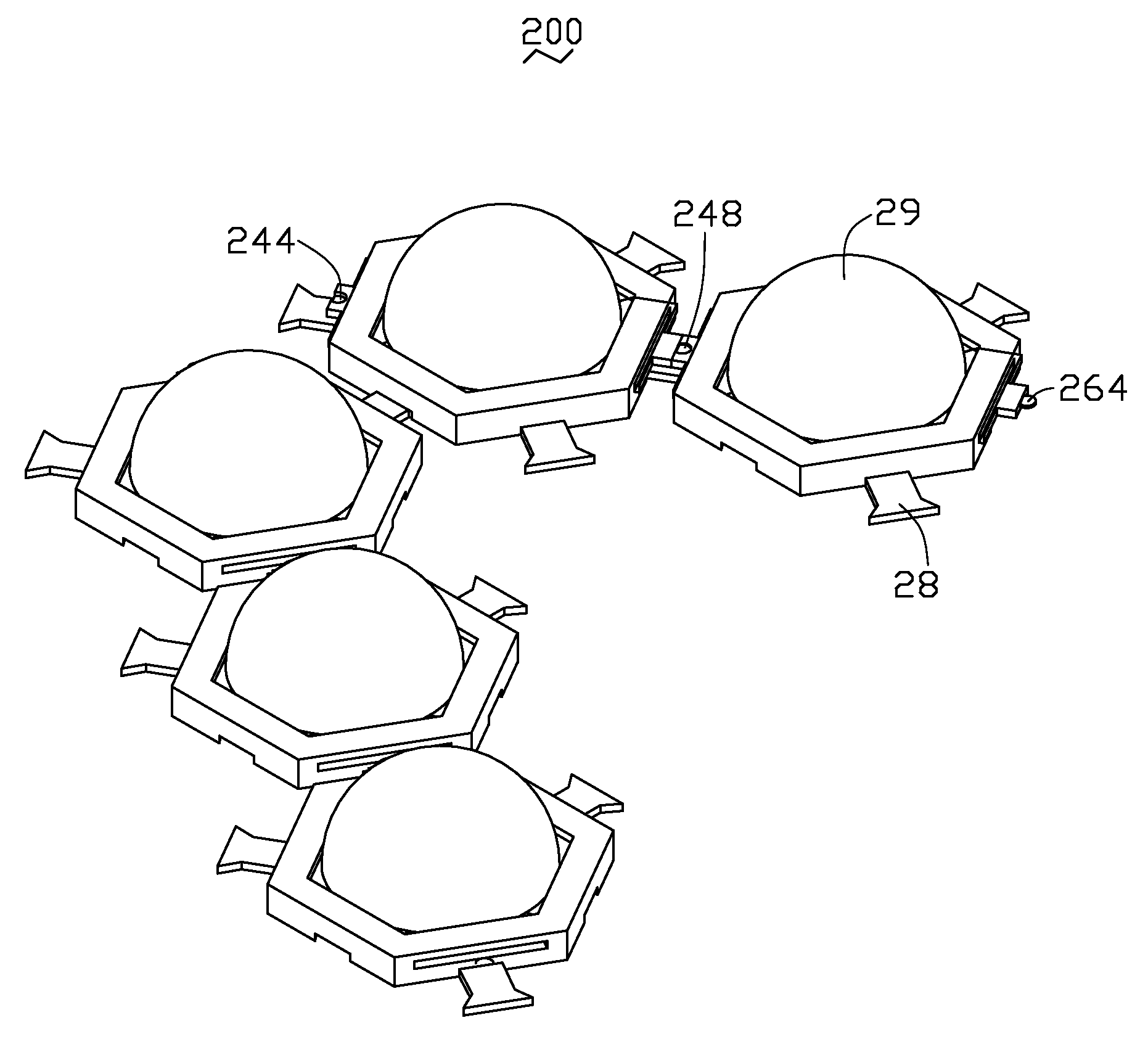
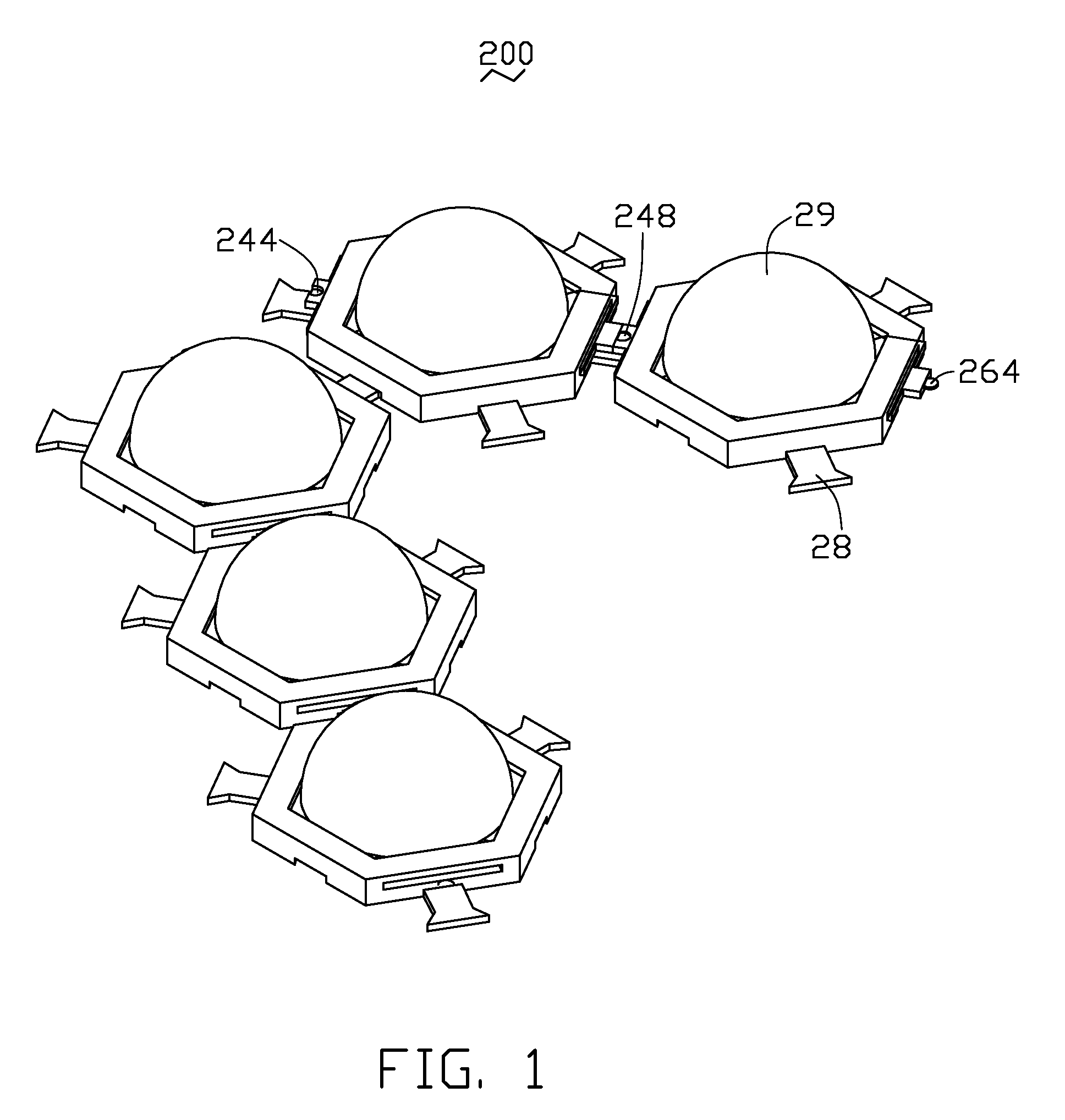
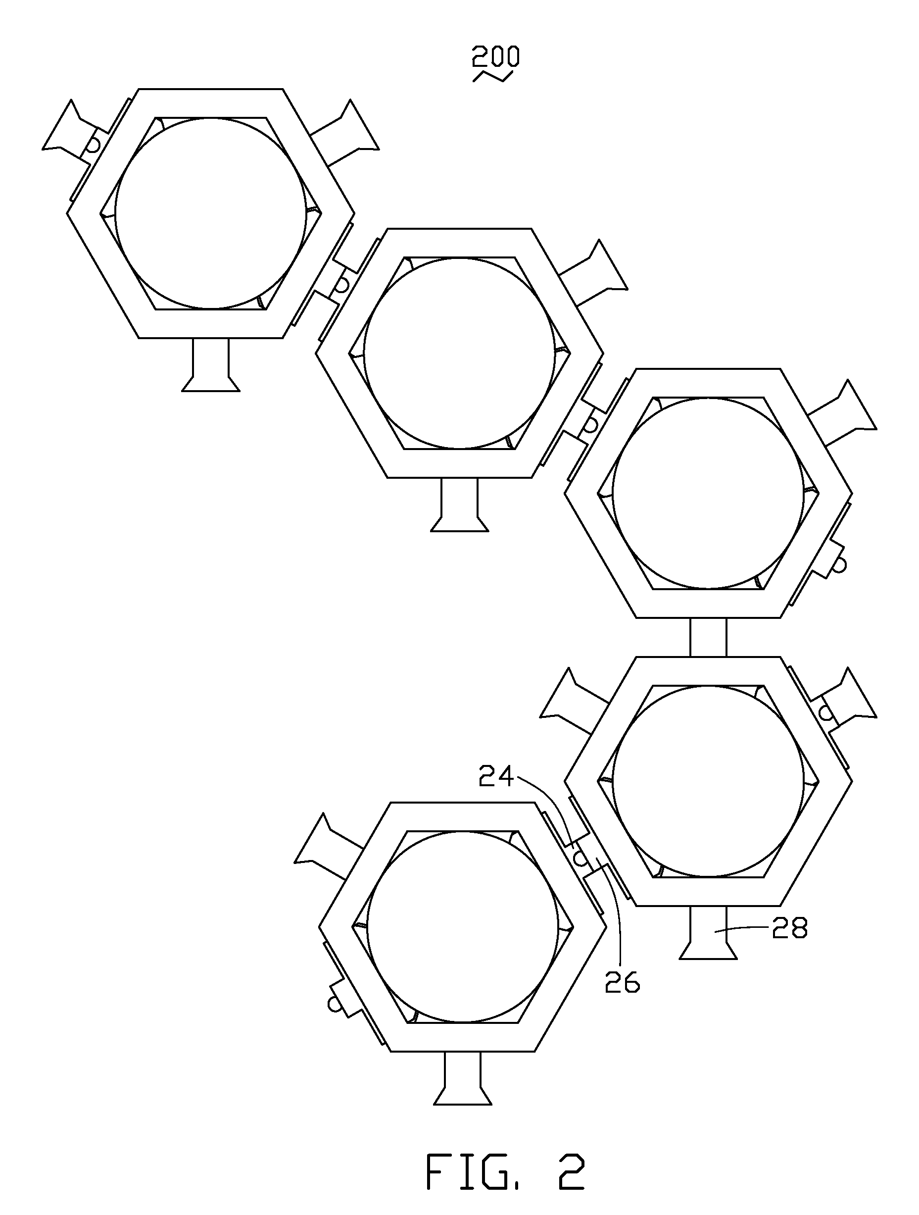
[0037]Also referring to FIGS. 4-7, the LED unit 200 is constructed by soldering a plurality of LEDs 20 together. Each LED 20 comprises a hexagonal base 22 defining a hexagonal cavity 220 therein, an LED die 23 adhesively attached in the cavity 220, a first electrode lead 24 and a second electrode lead 26 extending into the base 22 and electrically coupled to the LED die 23 via bonding wires (not shown), three legs 28 extending radially and outwardly from the base 22, and a hemispherical encapsulant 29 (see FIG. 1) encapsulating the LED die 23 therein. The base 22 is made of a material having a good heat conducting and electrically ...

eighth embodiment

[0052]Referring to FIG. 22, which shows an LED assembly in accordance with the present invention. In order to conduct heat generated by an LED die 23g to the substrate 10 more rapidly, a portion of a base 22g placed between the LED die 23g and the substrate 10 is omitted, while the LED die 23 is directly bonded on the top face of the substrate 10 via a kind of heat conducting adhesive 25g. Preferably, a thickness of the heat conducting adhesive 25g is selected to be less than 0.01 inches, for obtaining a balance between a good heat conducting capability and a sufficient gluing force. The base 22g of each LED 20g is annular to spacedly surround the LED die 23g. A first lead 24g and a second lead 26g are respectively inserted into the base 22g with inner parts (not labeled) thereof being exposed and outer parts (not labeled) thereof hovering above the substrate 10. The LED die 23g is electrically connected to the first and second leads 24g, 26g via golden wires (not labeled). An encap...


PUM


Abstract

An LED assembly includes a substrate and a plurality of LEDs mounted on the substrate. Each LED comprises an LED die, a base supporting the LED die thereon and thermally contacting the substrate to take heat generated by the LED die to the substrate, a pair of leads electrically connecting the LED die to input a current to the LED die, and an encapsulant enveloping the LED die. The pair of leads hover above the substrate to separate an electrical route of the LED assembly from a heat conducting pathway thereof. Furthermore, each LED has a plurality of legs extending raidally from the base thereof to fit in the base of an adjacent LED, to thereby engagingly lock with the adjacent LED.

Description

BACKGROUND OF THE INVENTION[0001]1. Field of the Invention[0002]The present invention relates to a light emitting diode (LED) assembly, and more particularly to an LED assembly having separated thermal and electrical structures for ensuring a constant lighting brightness and a long lifetime thereof.[0003]2. Description of Related Art[0004]LED have been available since the early 1960's. Because of the relatively high efficiency of LEDs, nowadays LED usage has been increased in popularity in a variety of applications, e.g., residential, traffic, commercial, industrial settings. However, when the LED is in operation, it generates a great deal of heat, which may result in the LED overheating or even malfunction if the heat cannot be dissipated timely. Therefore, many attempts are tried in order to effectively cool the LED.[0005]U.S. Pat. No. 6,561,680 B1 discloses a type of LED assembly, which comprises a metal substrate and an LED attached on the substrate (see FIG. 1B of U.S. Pat. No....

Claims


Application Information

Patent Timeline
IPC IPC(8): H01L33/00H01L33/48H01L33/62
CPCF21K9/00F21S2/005H01L33/486H01L33/62F21V19/005H01L2224/48247F21V29/20F21V29/006H01L2224/48091H01L2924/00014F21V29/51
Inventor KU, CHIN-LONG
Owner HON HAI PRECISION IND CO LTD
Why Eureka
Try Eureka