Internal voltage generator

a generator and internal voltage technology, applied in the direction of power conversion systems, instruments, process and machine control, etc., can solve the problems of increasing the overall current consumption, difficult to secure a stable operation performance, and sometimes the internal voltage rises excessively high than the desired value, so as to achieve stable internal voltage and less current consumption

Active Publication Date: 2009-09-24
SK HYNIX INC
View PDF3 Cites 5 Cited by
  • Summary
  • Abstract
  • Description
  • Claims
  • Application Information

AI Technical Summary

Benefits of technology

[0022]It is, therefore, an object of the present invention to provide an internal voltage generator which can supply a stable internal voltage with less current consumption.

Problems solved by technology

Meanwhile, an internal voltage sometimes ascends excessively higher than a desired value due to response characteristics of pull-up and pull-down drivers in a generally used internal voltage supplying device or due to differences in circuit configurations and operational environments.
Various defects may result because of the unstable internal voltage.
Especially, defects related to changes of the internal voltage react sensitively to the operational environments, and thus, it is difficult to secure a stable operation performance.
In this case, a consumption of a direct current Idirect occurs between the pull-down driver PM1 and the pull-up driver NM1, and thus, it creates an overall increase in current consumption, and leads to deterioration of the product competitiveness.
Therefore, the additional current consumption cannot be avoided.

Method used


Image

  • Internal voltage generator
  • Internal voltage generator
  • Internal voltage generator

Examples


first embodiment

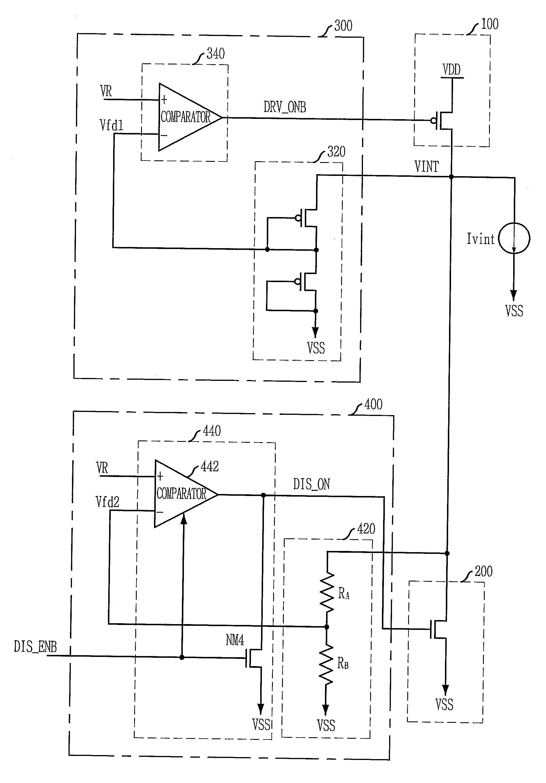
[0037]FIG. 3 is a circuit diagram of an internal voltage generator in accordance with the present invention. The internal voltage generator includes a pull-up driver 100 for pull-up driving a supply terminal of an internal voltage VINT, a pull-down driver 200 for pull-down driving the supply terminal of the internal voltage VINT, a pull-up driving control unit 300 for turning on the pull-up driver 100 when a first feedback voltage Vfd1 corresponding to the internal voltage VINT becomes lower than a reference voltage VR, and a pull-down driving control unit 400 for turning on the pull-down driver 200 when a second feedback voltage Vfd2 becomes higher than the reference voltage VR, the second feedback voltage Vfd2 having a voltage level which corresponds to the internal voltage VINT and is lower than the first feedback voltage Vfd1.

[0038]The pull-up driving control unit 300 includes a first feedback unit 320 for generating the first feedback voltage Vfd1 having a uniform voltage level...

second embodiment

[0052]FIG. 5 is a circuit diagram of an internal voltage generator in accordance with the present invention. The internal voltage generator includes a pull-up driver 100 for pull-up driving a supply terminal of an internal voltage VINT, a pull-down driver 200 for pull-down driving the supply terminal of the internal voltage VINT, a pull-up driving control unit 300 for turning on the pull-up driver 100 when a first feedback voltage Vfd1 corresponding to the internal voltage VINT becomes lower than a reference voltage VR, and a pull-down driving control unit 400. The pull-down driving control unit 400 includes a test unit 480 for generating selection signals (SEL1 to M), a second feedback unit 460 for transferring a voltage level selected from a plurality of voltage levels corresponding to the internal voltage VINT to a second feedback voltage Vfd2 in response to selection signals (SEL0 to 5), and a second control signal generating unit 440 for turning on the pull-down driver 200 when...


PUM


Abstract

An internal voltage generator includes a pull-up driver to pull-up drive a supply terminal of an internal voltage, a pull-down driver to pull-down drive the supply terminal of the internal voltage, a pull-up driving control unit to turn on the pull-up driver when a first feedback voltage corresponding to the internal voltage becomes lower than a reference voltage, and a pull-down driving control unit to turn on the pull-down driver when a second feedback voltage becomes higher than the reference voltage, the second feedback voltage having a voltage level corresponding to that of the internal voltage and lower than that of the first feedback voltage.

Description

PRIORITY[0001]This application is a division of U.S. patent application Ser. No. 11 / 529,253 filed on Sep. 29, 2006, which claims priority of Korean patent application number 2005-0091678 filed on Sep. 29, 2005 and Korean patent application number 2005-0133959 filed on Dec. 29, 2005. The disclosure of each of the foregoing applications is incorporated herein by reference in its entirety.FIELD OF THE INVENTION[0002]The present invention relates to a semiconductor device fabrication technology, and more particularly, to an internal voltage generator.DESCRIPTION OF RELATED ARTS[0003]A supply voltage of a semiconductor memory device has decreased, and thus, various technologies have been introduced to obtain stable memory operation characteristics. Various types of internal voltage supplying devices using a double voltage down converter have been developed into a form of technology.[0004]Meanwhile, an internal voltage sometimes ascends excessively higher than a desired value due to respo...

Claims


Application Information

Patent Timeline
Patent Type & Authority Applications(United States)
IPC IPC(8): G05F1/10
CPCG05F1/465
Inventor DO, CHANG-HO
Owner SK HYNIX INC
Why Eureka
Try Eureka