Recognition system for vehicle

Inactive Publication Date: 2009-09-24
DENSO CORP
View PDF22 Cites 87 Cited by
  • Summary
  • Abstract
  • Description
  • Claims
  • Application Information

AI Technical Summary

Benefits of technology

[0005]It is therefore an object of the invention to provide a recognition system, wherein the accuracy of position information tra

Problems solved by technology

In this system information acquired from the other vehicle usually includes an error, and hence uses in which the information can be utilized are limited.
This is because in

Method used


Image

  • Recognition system for vehicle
  • Recognition system for vehicle
  • Recognition system for vehicle

Examples


Embodiment Construction

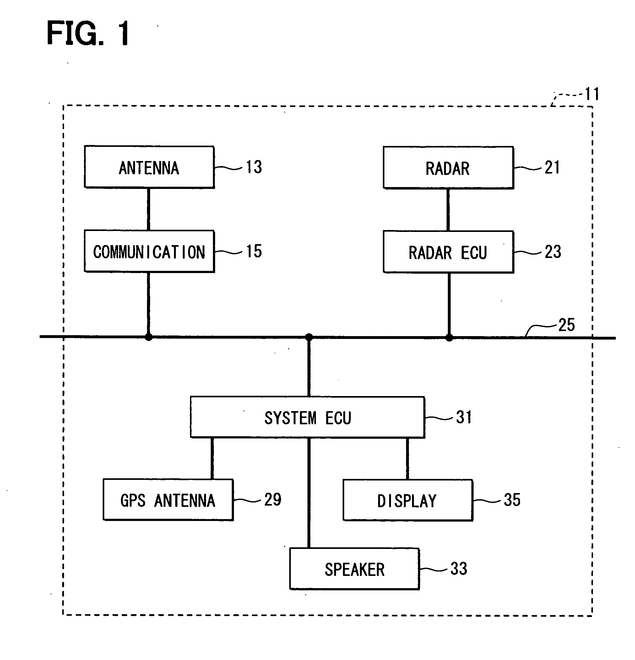
[0021]Referring first to FIG. 1, an inter-vehicle communication device 11 equipped and used in a vehicle includes a communication antenna 13, a communication control ECU 15, a radar 21, a radar control ECU 23, a vehicle LAN 25, a GPS antenna 29, a system control ECU 31, a speaker 33 and a display 35. The antenna 13 and ECU 15 operate as first communicating means mounted in one vehicle and second communicating means mounted in another vehicle.

[0022]The communication antenna 13 transmits and receives radio waves for communication with other inter-vehicle communication devices 11 and is controlled by the communication control ECU 15. From the communication antenna 13, radio waves with a range of a few tens of meters to a few hundreds of meters are outputted.

[0023]The communication control ECU 15 generates transmission signals based on data received through the vehicle LAN 25 and causes the communication antenna 13 to transmit the signals as radio waves. The communication control ECU th...


PUM


Abstract

In a recognition system for a vehicle, forward vehicle information and infrastructural information are checked together and with respect to information that can be considered to pertain to one and the same vehicle. Pieces of information on position and speed are averaged to acquire the information of the vehicle. Pieces of information that can be considered to pertain to one and the same vehicle are searched for and integrated into one. Further, estimated values of speed and position in the future are corrected using traveling information. Then identical lane probability and collision time are estimated, and information of the subject vehicle is transmitted to a vehicle on a potential collision course.

Description

CROSS REFERENCE TO RELATED APPLICATION[0001]This application is based on and incorporates herein by reference Japanese Patent Application No. 2008-74043 filed on Mar. 21, 2008.FIELD OF THE INVENTION[0002]The present invention relates to a system that recognizes objects.BACKGROUND OF THE INVENTION[0003]In some conventional systems, a subject vehicle acquires the position information of the other vehicle near the subject vehicle from the communication device equipped in the other vehicle and notify the user, as disclosed in US 2005 / 0225457 A (JP 2005-301581 A). This system is so configured that each vehicle measures its own position based on information acquired from GPS (Global Positioning System) and the position information acquired by this measurement is utilized.[0004]In this system information acquired from the other vehicle usually includes an error, and hence uses in which the information can be utilized are limited. This is because information acquired by checking together pi...

Claims


Application Information

Patent Timeline
IPC IPC(8): G08G1/16G01S13/06G01S13/931
CPCG01S5/0072G01S13/86G01S13/931G01S2013/936G08G1/163G01S2013/9353G01S2205/002G01S2013/932G01S2013/9316
Inventor SAKUMA, YASUSHI
Owner DENSO CORP
Why Eureka
Try Eureka