
Mountable apparatus, board, and method of rewriting liquid information

a technology of liquid information and mounting apparatus, which is applied in the field of mounting apparatus, a board, and a method of rewriting liquid information, can solve the problems of data corruption, hampered normal read/write operations to the memory, and the printer will attempt to access the memory while it is being rewritten

Active Publication Date: 2009-09-24
SEIKO EPSON CORP
View PDF6 Cites 4 Cited by
  • Summary
  • Abstract
  • Description
  • Claims
  • Application Information

AI Technical Summary

Benefits of technology

[0007]It is accordingly one object of the present invention to limit the occurrence of difficulties caused by a liquid jetting device operating at times that a task is being performed in relation to a mountable apparatus or a liquid container, while the mountable apparatus is installed in the liquid jetting device.
[0008]A first aspect of the present invention provides a mountable apparatus adapted for installation in a liquid jetting device when delivering a liquid contained in a liquid container that contains a liquid to the liquid jetting device via a liquid delivery tube connected to the liquid container. The mountable apparatus includes an installation status notifier portion that, in an installed state wherein the mountable apparatus is installed in the liquid jetting device, is able to make the liquid jetting device determine that there exists the installed state, and alternatively to make the liquid jetting device determine, even in the installed state, that there exists a non-installed state wherein the mountable apparatus is not installed in the liquid jetting device. According to this aspect, the liquid jetting device can be caused to determine that the mountable apparatus is not installed, even when the mountable apparatus is currently installed in the liquid jetting device. As a result, at times that some task is being performed in relation to the mountable apparatus or liquid container while the mountable apparatus remains installed in the liquid jetting device, the liquid jetting device can be prevented from carrying out operations that are enabled in the installed state, by causing it to determine that a non-installed state exists.
[0009]The mountable apparatus according to the first aspect may further include a memory adapted to allow the liquid jetting device to read and write liquid information relating to the liquid while in the installed state; and an information rewriting portion that rewrites the liquid information in the memory independently of a read or write operation by the liquid jetting device, wherein the installation status notifier portion may make the liquid jetting device determine that there exists the non-installed state while the information rewriting portion is rewriting the liquid information. With this arrangement, the liquid jetting device can be prevented from accessing the memory during rewriting of liquid information in the memory independently of the liquid jetting device.

Problems solved by technology

However, if residual amount information in the memory should happen to be rewritten while the ink container is installed in the printer, there is a risk that the printer will attempt to access the memory while it is being rewritten.
If this should happen, normal read / write operations to the memory will be hampered, creating a risk of data corruption.
With this arrangement, the liquid jetting device will not be able to ascertain that the determination use terminal is in contact with the device-side terminal that corresponds to the determination use terminal, so the liquid jetting device can be caused to determine that a non-installed state exists.
With this arrangement, the liquid jetting device will not be able to receive a response signal from the output terminal, so the liquid jetting device can be caused to determine that a non-installed state exists.

Method used


Image

  • Mountable apparatus, board, and method of rewriting liquid information
  • Mountable apparatus, board, and method of rewriting liquid information
  • Mountable apparatus, board, and method of rewriting liquid information

Examples


embodiment 1

A. Embodiment 1

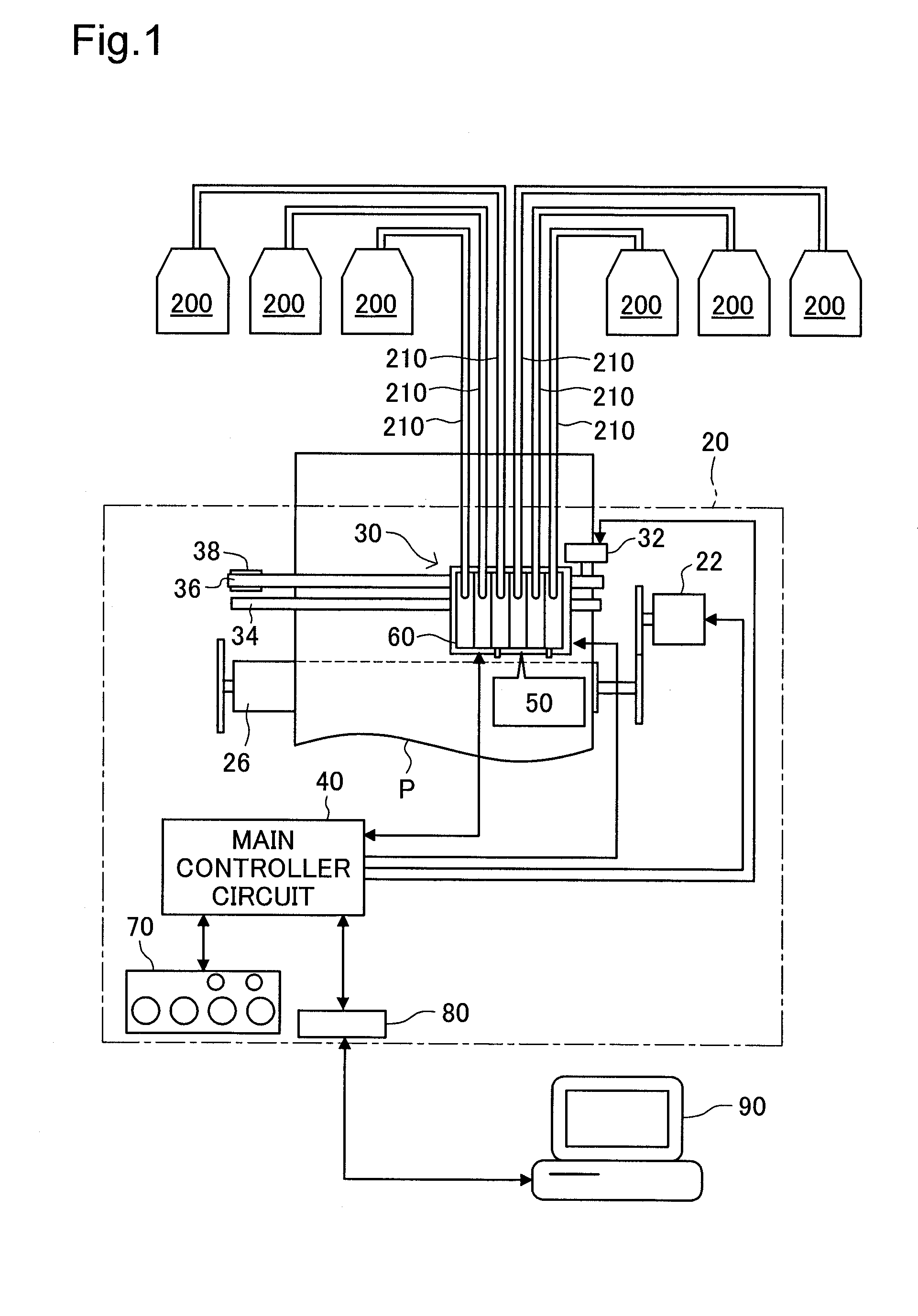
[0046]FIG. 1 is an illustration depicting a general configuration of a printing system according to an embodiment of the present invention. The printing system is furnished with a printer 20, a computer 90, and six ink containers 200. The printer 20 is connected to the computer 90 via a connector 80. Each of the six ink containers 200 contains ink of a different color. The six ink containers 200 are respectively connected to the printer 20 by single tubes 210. The tubes 210 provided as the ink delivery tubes are made of flexible material such as rubber or elastomer.

[0047]The printer 20 is furnished with a sub-scan feed mechanism, a main scan feed mechanism, a head driving mechanism, and a main controller circuit 40 for controlling these mechanisms. The sub-scan feed mechanism includes a paper feed motor 22 and a platen 26; rotation of the paper feed motor is transmitted to the platen in order to feed paper P in the sub-scanning direction. The main scan feed mechanism ...

embodiment 2

[0075]FIG. 9 is a diagram depicting an electrical configuration of an ink relay cartridge 100a and a printer 20 of Embodiment 2. The configuration of the printer 20 is identical to that in Embodiment 1 and will not be described here. The ink relay cartridge 100a of Embodiment 2 differs from that of Embodiment 1 in that it lacks a sensor 150; all nine of the terminals are instead connected to a controller 130b which is a logic circuit. The reset button 120a of the ink relay cartridge 100a of Embodiment 2 differs from that of Embodiment 1 in that it does not include the first switch SWa. In Embodiment 2, a sensor driving signal that the sensor access unit 53 has input via the sensor driving terminals SN, SP will be received by the controller 130b, which will always return a response signal indicating that ink 5 is present in the ink container 200. Additionally, in Embodiment 2, the controller 130a is furnished with a timer function adapted to measure a prescribed time interval.

[0076]F...

embodiment 3

C. Embodiment 3

[0079]FIG. 11 is a diagram depicting an electrical configuration of an ink relay cartridge 100b and a printer 20 of Embodiment 3. The configuration of the printer 20 is identical to that in Embodiment 1 and will not be described here. The ink relay cartridge 100b of Embodiment 3 differs from that of Embodiment 1 in that it lacks the reset button 120; instead, the first cartridge out terminal COA and the ground terminal VSS are connected to a controller 130b which is a logic circuit. Other arrangements are the same as in Embodiment 1.

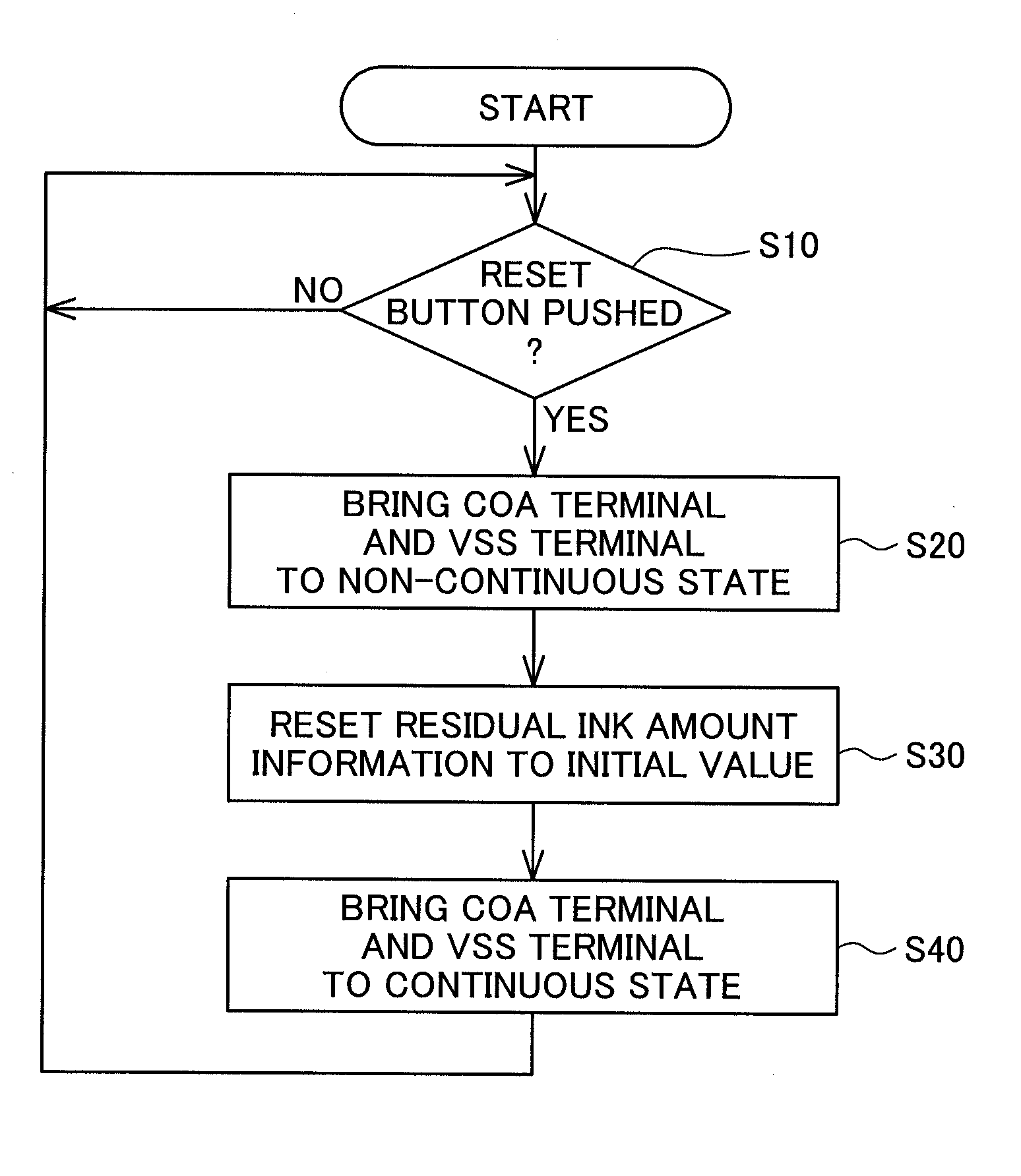
[0080]FIG. 12 is a flowchart showing the process steps of the reset process of Embodiment 3. With the ink relay cartridge 100b in the installed state, the controller 130b will check the residual ink amount information periodically or each time that the residual ink amount information is updated, to determine whether the residual ink amount information is equal to or less than a specified value (Step S210). If the residual ink amount inform...


PUM


Abstract

A mountable apparatus, which is adapted for installation in a liquid jetting device when delivering a liquid contained in a liquid container that contains a liquid to the liquid jetting device via a liquid delivery tube connected to the liquid container, includes an installation status notifier portion. In an installed state wherein the mountable apparatus is installed in the liquid jetting device, the installation status notifier portion is able to make the liquid jetting device determine that there exists the installed state, and alternatively to make the liquid jetting device determine, even in the installed state, that there exists a non-installed state wherein the mountable apparatus is not installed in the liquid jetting device.

Description

CROSS REFERENCE TO RELATED APPLICATIONS[0001]This application relates to Japanese Patent Applications No. 2008-63581, filed on Mar. 13, 2008 and No. 2009-53449, filed on Mar. 6, 2009, the entire disclosure of which is incorporated by reference.BACKGROUND[0002]1. Technical Field[0003]The present invention relates to a mountable apparatus, a board, and a method of rewriting liquid information.[0004]2. Description of the Related Art[0005]A typical inkjet printer is equipped with one or more ink containers containing ink. In one known technology relating to ink containers that have on-board memory for recording residual amount information indicating residual ink amount, the ink container is provided with a reset button which is pushed when the ink container has been refilled with ink. According to this technology, when the reset button is pushed, the residual amount information in the memory will be rewritten so as to ensure correct operation of the printer.[0006]However, if residual am...

Claims


Application Information

Patent Timeline
IPC IPC(8): B41J29/393
CPCB41J2/17546B41J2/17509
Inventor ISHIZAWA, TAKUSHINADA, SATOSHI
Owner SEIKO EPSON CORP
Learn More