
Retardation film

a technology of retardation film and film body, which is applied in the direction of polarising elements, instruments, chemistry apparatus and processes, etc., can solve the problems of sometimes caused deviation of birefringence compensation, and achieve excellent durability

Active Publication Date: 2009-09-24
ZEON CORP
View PDF2 Cites 12 Cited by
  • Summary
  • Abstract
  • Description
  • Claims
  • Application Information

AI Technical Summary

Benefits of technology

[0018]Using a retardation film of the present invention can provide a liquid crystal display device of which a birefringence compensation doesn't change even if it is left under a hot-environment and which has an excellent durability.

Problems solved by technology

However, as for the retardation films described in the patent documents, a deviation of a birefringence compensation is occasionally caused because the retardation value of the retardation film changes if the retardation film is left under a hot environment.

Method used


Image

  • Retardation film
  • Retardation film

Examples


example 1

[0103]The laminate E1 which was obtained in PRODUCING EXAMPLE 1 was supplied to a longitudinal uniaxially stretching machine, and the laminate was stretched in a longitudinal direction at a stretching temperature of 145° C. by a draw ratio of 1.5.

[0104]Then, the longitudinal uniaxially stretched film was supplied to a tenter stretching machine, the film was stretched in a transverse direction at a stretching temperature of 130° C. by a draw ratio of 1.25 to obtain a retardation film R1.

[0105]A retardation film R1 was stretched by draw ratio of 1.25 in one direction (for example, the direction of 0 degree against a direction of the longitudinal stretching being X axis) at the temperature described in Table 2. Then, a lag in a phase of linearly polarized light ΨX′ entering at the incident angle of 0 degree and having an oscillating surface of an electric vector in an X-Z plane against a phase of linearly polarized light ΨY′ entering at the incident angle of 0 degree and having an osci...

example 2

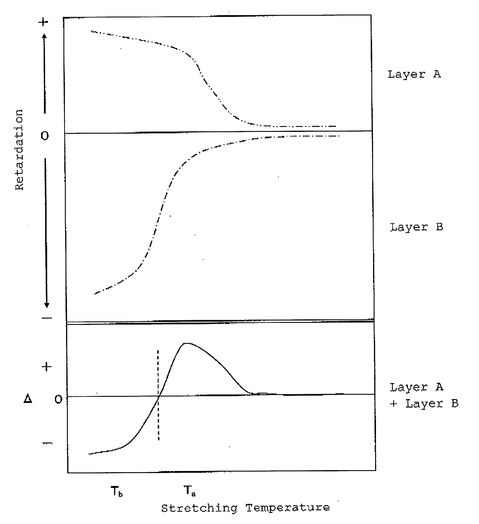
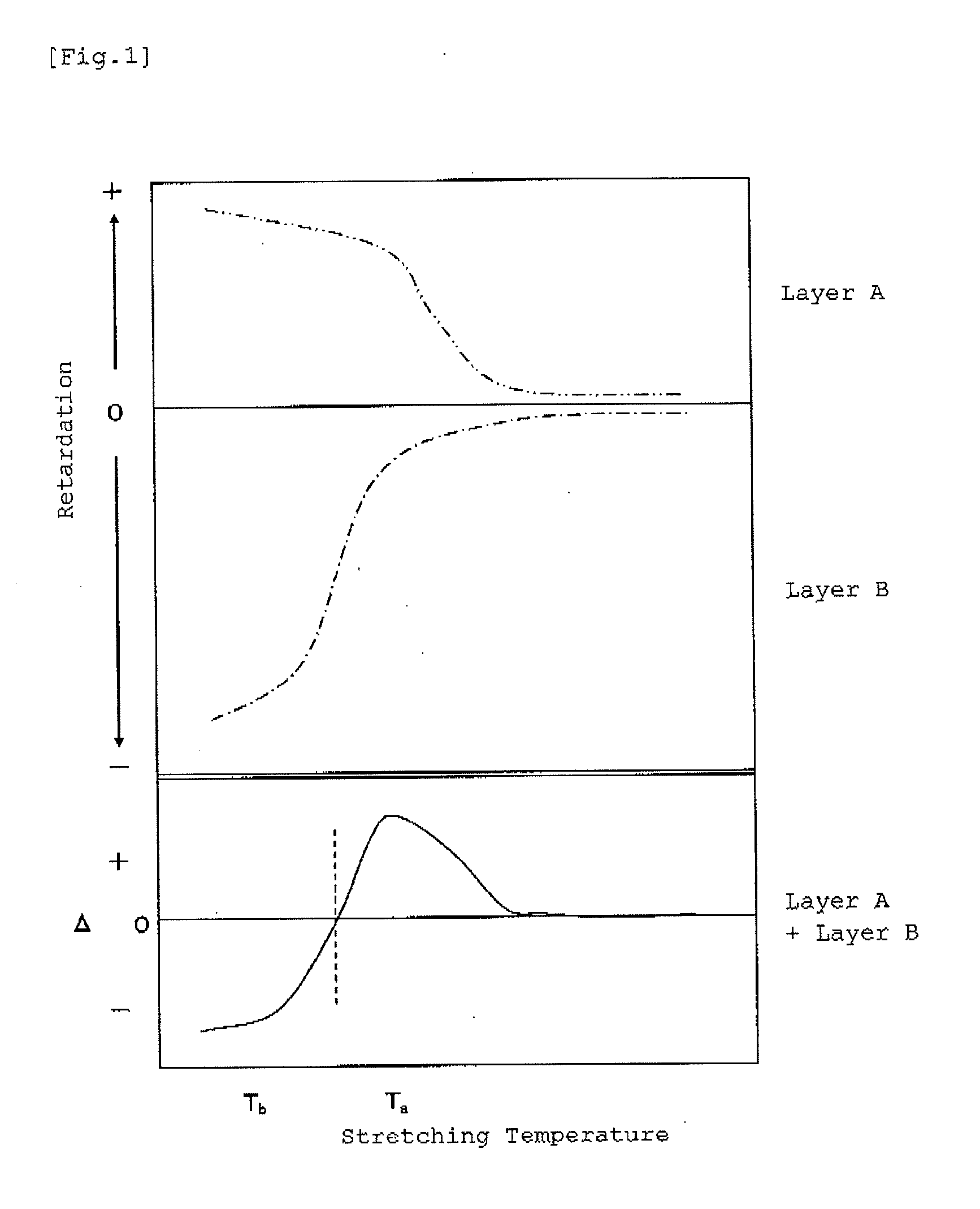
[0107]A retardation film R2 was obtained in the same manner as in EXAMPLE 1, except that draw ratio in a transverse direction was changed to 1.5. The retardation film R2 had a characteristic that a phase was delayed by 80 nm against a phase before stretching in case of stretching at 145° C., and a phase was hastened by 117 nm against a phase before stretching in case of stretching at 130° C. The retardation film R2 was 1.006 in R40 / Re, and satisfied the relation of 0.92≦R40 / Re≦1.08. Table 2 shows the result of the durability test on the retardation film R2.


PUM

PropertyMeasurementUnit
Temperatureaaaaaaaaaa
Angleaaaaaaaaaa
Angleaaaaaaaaaa

Abstract

A retardation film composed of a laminated film which comprises a layer A composed of a material having a positive intrinsic birefringence and a deflection temperature under load of Ts(A) and a layer B composed of a material having a negative intrinsic birefringence and a deflection temperature under load of Ts(B), in which a difference between Ts(A) and Ts(B) is 5° C. or more; the retardation film has a stretching temperature Tα which causes delaying of a phase after the stretching to a phase before the stretching and a stretching temperature Tβ which causes hastening of a phase after the stretching to a phase before the stretching, in cases of uniaxially stretching in a direction of an X axis by draw ratio of 1.25 at temperature in the range that the retardation film can be stretched, in which the phase is of linearly polarized light ΨX having an oscillating surface of an electric vector in an X-Z plane and entering at an incident angle of 0 degree in relation to linearly polarized light ΨY having an oscillating surface of an electric vector in a Y-Z plane and entering at an incident angle of 0 degree, the X axis is an uniaxially stretching direction, the Y axis is a direction perpendicular to a direction of the X axis in the film plane, and the Z axis is a direction of a thickness of the film; and the retardation film meets a relation of 0.92≦R40 / Re≦1.08, wherein Re (nm) is a retardation value of light having a wavelength of 550 nm at an incident angle of 0 degree, and R40 (nm) is a retardation value of light having a wavelength of 550 nm at an incident angle of 40 degrees.

Description

TECHNICAL FIELD[0001]The present invention relates to a retardation film.[0002]More particularly, the present invention relates to a retardation film in which a birefringence compensation in a liquid crystal display device doesn't change even if the retardation film is left under a hot environment.BACKGROUND OF THE ART[0003]To decrease a dependence of a color tone of a liquid crystal display device on an angle, a retardation film which meets a relation of 0.92≦R40 / Re≦1.08, wherein Re is a retardation value at an incident angle of 0 degree and R40 is a retardation value at an incident angle of 40 degrees, or a retardation film which meets a relation of nx>nz>ny, wherein nx is a refractive index in a direction of a slow axis in a plane of the film, ny is a refractive index in a direction perpendicular to the direction of the slow axis in the plane, nz is a refractive index in a thickness direction has been proposed.[0004]For example, Patent Document 1 discloses that a first anis...

Claims


Application Information

Patent Timeline
IPC IPC(8): G02B1/08B32B37/14
CPCG02F2203/60G02B5/3083
Inventor HATANO, TAKUYAMANAKA, SHUNSUKE
Owner ZEON CORP
Learn More