Optical Signal Transmission Apparatus

a technology of optical amplifiers and optical signals, applied in the field of optical signal transmission apparatuses, can solve the problems of increased loss between optical amplifiers, multi-fiber stocking, and bit error of received signals

Inactive Publication Date: 2009-09-24
HITACHI LTD
View PDF10 Cites 26 Cited by
  • Summary
  • Abstract
  • Description
  • Claims
  • Application Information

AI Technical Summary

Benefits of technology

[0012]In order to solve the above-mentioned problem, there is provided an optical signal transmission apparatus that controls a variable dispersion compensator by using information to determine a factor for the bit error in addition to a bit error of a received signal so as not to vary a compensation value of the variable dispersion compensator even if a bit error increases when a signal quality is deteriorated due to factors other than the dispersion of a fiber As the information to determine the factor for the bit error, optical noise information and received optical power information may be used.
[0013]In one aspect, an optical signal transmission apparatus includes an optical signal transmitter unit; a variable dispersion compensator that adjusts a dispersion compensation amount to compensate waveform distortion caused by dispersion of an optical fiber; a control unit that controls the dispersion compensation amount of the variable dispersion compensator; a control mode determination unit that designates a control content of the control unit; an optical receiver unit; and a signal quality supervisory unit, wherein the control mode determination unit determines whether or not an optical signal power is within a proper range on the basis of optical power information received from the optical reception unit, and the control unit controls the variable dispersion compensator on the basis of a determination re

Problems solved by technology

However, in the fixed dispersion compensator, there is a problem that plural fibers must be stocked.
However, the bit error of the received signal may occur due to a factor other than dispersion.
As another example, since temporary tension is involuntarily applied to a fiber due to device installation work in the vicinity of a device, a loss between optical amplifiers increases and an optical signal-to-noise ratio (OSNR) is deteriorated, whereby the bit error is generated.
In this case, when the variable dispersion compensator is controlled only by the bit error information of the received

Method used


Image

  • Optical Signal Transmission Apparatus
  • Optical Signal Transmission Apparatus
  • Optical Signal Transmission Apparatus

Examples


Embodiment Construction

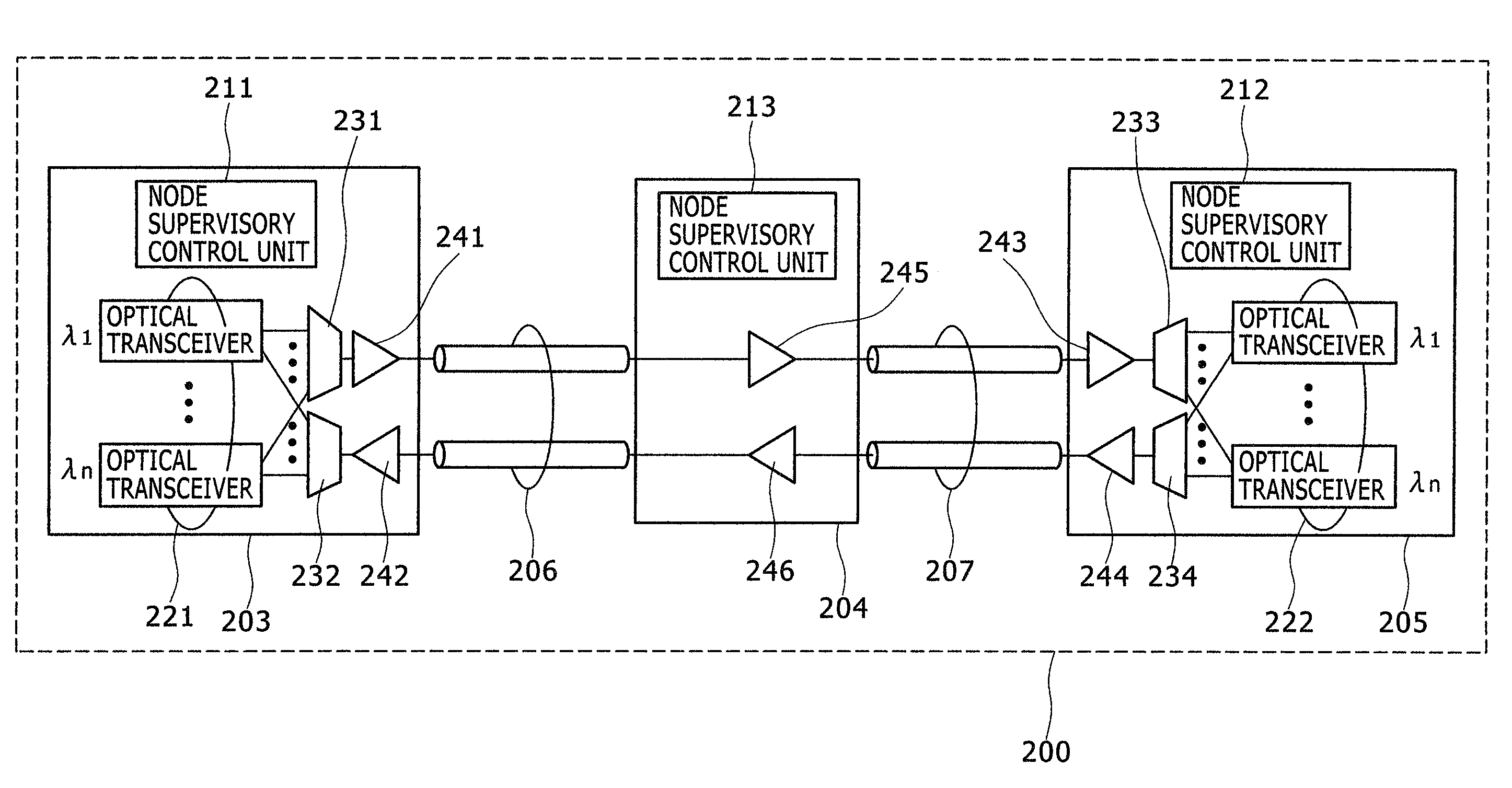
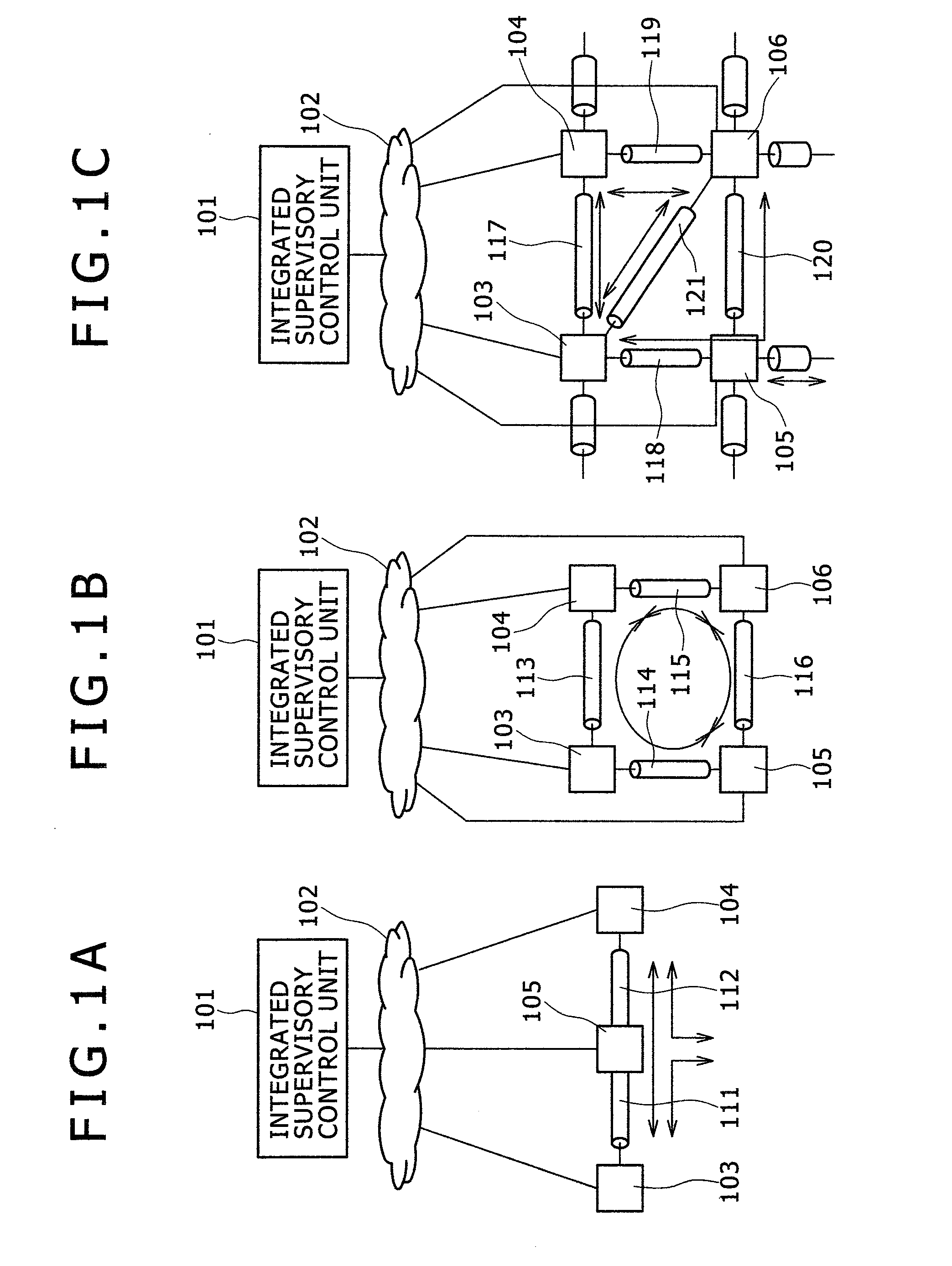
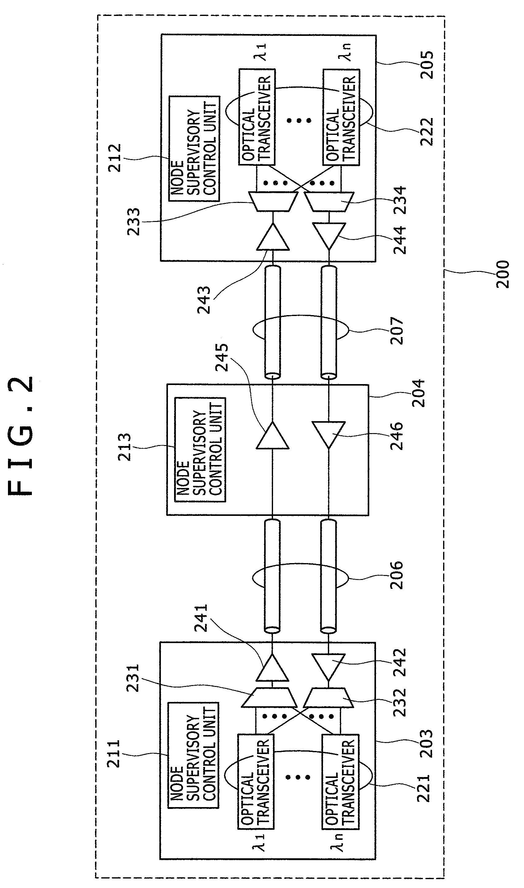
[0026]Hereinafter, modes of the present invention will be described with reference to the accompanying drawings using the embodiments. FIGS. 1A to 1C are block diagrams illustrating a network configuration. FIG. 2 is a block diagram of an optical transmission apparatus. FIG. 3 is a block diagram of another optical transmission apparatus. FIGS. 4A to 4C are pattern diagrams illustrating an effect of a dispersion compensator. FIG. 5 is a block diagram illustrating the configuration of an optical transceiver. FIG. 6 is a block diagram illustrating the configuration of an optical transceiver in detail. FIG. 7 is a flowchart illustrating the operation of an optical signal transmission apparatus when a path is opened. FIG. 8 is a flowchart illustrating the operation of an optical signal transmission apparatus until a path is deleted in operation. FIG. 9 is a diagram illustrating the condition of a control mode determination unit. FIG. 10 is a diagram illustrating the state transition of a...


PUM


Abstract

There is provided an optical signal transmission apparatus having a stable dispersion compensation function without unnecessarily controlling a compensation value even when a main signal quality is deteriorated due to a factor other than dispersion or in the case of a transmission failure. When it is determined that a signal quality is deteriorated due to dispersion of a fiber by determining a control mode of a variable dispersion compensator by means of optical noise information and received power information in addition to bit error information of a received signal, a compensation value of the variable dispersion compensator is varied and a compensation value other than the dispersion of the optical fiber is held to an existing set value.

Description

CLAIM OF PRIORITY[0001]The present application claims priority from Japanese patent application serial no. 2008-074034, filed on Mar. 21, 2008, the content of which is hereby incorporated by reference into this application.BACKGROUND OF THE INVENTION[0002]The present invention relates to an optical signal transmission apparatus, and more particularly, to an optical signal transmission apparatus having a dispersion compensation function of compensating a waveform that is distorted due to the dispersion of optical fibers.[0003]Due to rapid increase of data traffic representative on the Internet, an optical communication network for enabling large-capacity communication is required. In order to implement large-capacity communication, a wavelength division multiplexing (WDM) technology is used. In the WDM technology, several tens of wavelengths can be transmitted through one optical fiber. Long-range transmission over several hundreds of kilometers is available by using optical amplifie...

Claims


Application Information

Patent Timeline
IPC IPC(8): H04B10/08H04B10/2507H04B10/077H04B10/079H04B10/2513H04B10/2519H04B10/2525H04B10/2569H04B10/275H04B10/278H04B10/299H04B10/524H04B10/54H04B10/556H04B10/572H04B10/58H04B10/60H04J14/00H04J14/02
CPCH04B10/0775H04B2210/252H04B2210/078H04B10/07953
Inventor FUKASHIRO, YASUYUKIMIYASAKA, EITA
Owner HITACHI LTD
Why Eureka
Try Eureka