Toner-density calculating method, reflective optical sensor, reflective optical sensor device, and image forming apparatus

a technology of toner density and calculating method, applied in the direction of optical radiation measurement, instruments, specific gravity measurement, etc., can solve the problems of difficult to always keep, difficult toner density measurement, and distortion of toner imag

Inactive Publication Date: 2009-09-24
RICOH KK
View PDF24 Cites 42 Cited by
  • Summary
  • Abstract
  • Description
  • Claims
  • Application Information

AI Technical Summary

Benefits of technology

[0020]It is an object of the present invention to at lea...

Problems solved by technology

If the toner density is high, i.e., if the amount of the toner supplied to the electrostatic latent image is more than the necessary amount, a darker and difficult-to-see toner image will be formed.
However, it is difficult to always keep a relative position between the toner pattern and the reflective optical sensor in the main-direction the ideal state, due to various reasons.
If a portion of the spot falls in a region where there is no toner pattern because of the positional miss-match in the main-direction between the toner pattern and the reflective optical sensor, the reflected light received by the light-receiving unit represents wrong data, and therefore the measured toner density is wrong.
Because the toner-density measurement is per...

Method used


Image

  • Toner-density calculating method, reflective optical sensor, reflective optical sensor device, and image forming apparatus
  • Toner-density calculating method, reflective optical sensor, reflective optical sensor device, and image forming apparatus
  • Toner-density calculating method, reflective optical sensor, reflective optical sensor device, and image forming apparatus

Examples


first embodiment

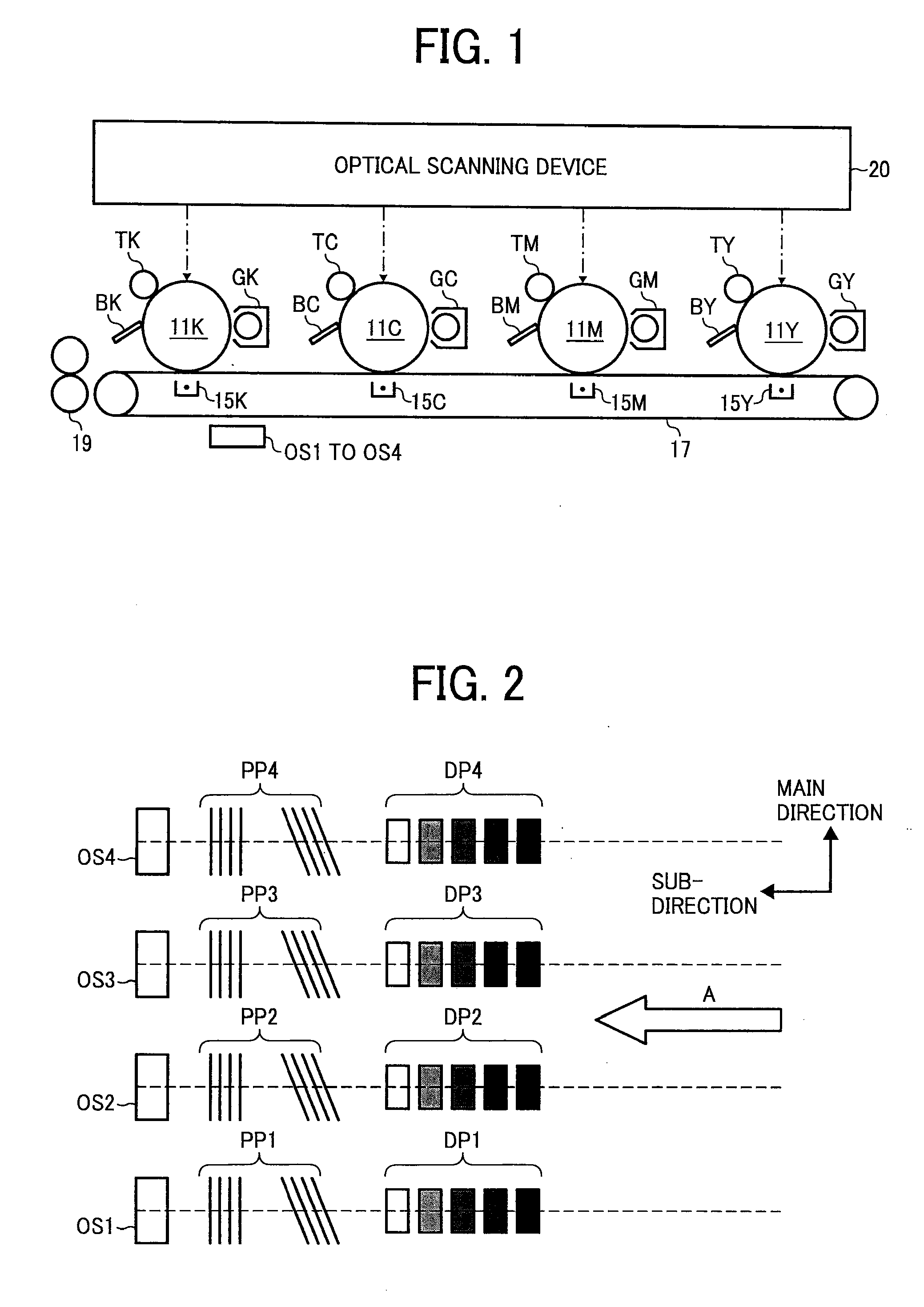
[0070]An image forming apparatus according to the present invention is described with reference to FIG. 1.

[0071]The image forming apparatus illustrated in FIG. 1 is a color image forming apparatus; however, the following description will apply even to a monochrome image forming apparatus. A color image is formed with four toners including yellow (Y), magenta (M), cyan (C), and black (K).

[0072]The image forming apparatus includes an optical scanning device 20. The optical scanning device 20 can be any widely-known scanner.

[0073]The image forming apparatus includes drum-shaped photosensitive elements 11Y, 11M, 11C, and 11K as photoconductive latent-image carriers. The photosensitive element 11Y is used for forming a yellow toner image, the photosensitive element 11M is for a magenta toner image, the photosensitive element 11C is for a cyan toner image, and the photosensitive element 11K is for a black toner image.

[0074]The optical scanning device 20 writes images onto the photosensiti...

second embodiment

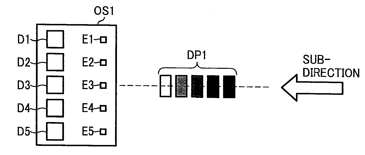
[0155]In the second embodiment illustrated in FIG. 4A, the light-emitting elements E1 to E15 and the light-receiving elements D1 to D15 that are aligned in the main-direction sequentially with beginning with the light-emitting element E1 and the light-receiving element D1. Moreover, the light-emitting elements E1 to E15 and the light-receiving elements D1 to D15 that are divided into a first group, a second group, and a third group. The first group includes the light-emitting elements E1 to E5 and the light-receiving elements D1 to D5; the second group includes the light-emitting elements E6 to E10 and the light-receiving elements D6 to D10; and the third group includes the light-emitting elements E11 to E15 and the light-receiving elements D11 to D15. The light-emitting elements of each group are aligned in a single line, and the light-receiving elements of each group are aligned in a single line. When the reflective optical sensor is in position to measure the toner density, the l...

third embodiment

[0159]In the third embodiment illustrated in FIG. 4B, when the reflective optical sensor is in position to measure the toner density, the light-emitting elements E1 to E15 and the light-receiving elements D1 to D15 are aligned in a single direction that is inclined to the main-direction at an angle α. The angle α is decided based on the velocity of the supporting member moving in the sub-direction.

[0160]More particularly, if the angle α satisfies a following Equation:

Z·tan α=V·st

where st is scanning time, Z is the length in the main-direction of lines on which the light-emitting elements E1 to E15 and the light-receiving elements D1 to D15 are aligned, then the spot scanning of the toner pattern by the light-emitting elements E1 to E15 is completed within the scanning time.


PUM


Abstract

A toner density is calculated from outputs of light-receiving elements based on a difference between a reflection property of a supporting member and a reflection property of a toner pattern. Light-emitting elements aligned in one direction that is inclined to a sub-direction emit a detection light in such a manner that a distance between adjacent spots falling on the supporting member in a second direction is equal to or smaller than a width of the toner pattern in the second direction. The light-receiving elements receive a reflected light reflected from the supporting member and/or the toner pattern. The light-receiving elements are aligned, opposed to the supporting member, in a one direction corresponding to the light-emitting elements.

Description

CROSS-REFERENCE TO RELATED APPLICATIONS[0001]The present application claims priority to and incorporates by reference the entire contents of Japanese priority document 2008-070198 filed in Japan on Mar. 18, 2008 and Japanese priority document 2008-238451 filed in Japan on Sep. 17, 2008.BACKGROUND OF THE INVENTION[0002]1. Field of the Invention[0003]The present invention relates to a technology for calculating a toner density.[0004]2. Description of the Related Art[0005]A variety of image forming apparatuses use toner to form images, i.e., they form toner images. Example of such image forming apparatuses are analog image forming apparatuses, digital image forming apparatuses, black-and-white copiers, color copiers, printers, plotters, facsimile machines, and, multifunction printers (MFPs).[0006]To form a good quality toner image, as is widely known, an electrostatic latent image needs to be developed with just an appropriate amount of toner. The electrostatic latent image can be deve...

Claims


Application Information

Patent Timeline
IPC IPC(8): G03G15/00G01N9/36G01N21/55G01N21/47G03G15/01G03G15/08G03G21/00G03G21/14
CPCG03G15/0178G03G2215/00042G03G2215/00059G03G15/5058G01B11/14G01J1/42G03G15/556G03G15/5041G01B11/00G01J1/0238G01N21/55G03G11/00
Inventor MASUDA, KOJI
Owner RICOH KK
Why Eureka
Try Eureka