Buffer type vertebral pedicle screw

a pedicle screw and buffer technology, applied in the field of buffer type vertebral pedicle screw, can solve the problems of patient pain, patient deterioration, and inability to lead an active life, and achieve the effects of preventing shock or vibration, reducing pain of patients, and increasing overall efficiency of spine surgery

a pedicle screw and buffer technology, applied in the field of buffer type vertebral pedicle screw, can solve the problems of patient pain, patient deterioration, and inability to lead an active life, and achieve the effects of preventing shock or vibration, reducing pain of patients, and increasing overall efficiency of spine surgery

US20090240290A1Inactive Publication Date: 2009-09-24CHOI GIL WOON

Image

  • Buffer type vertebral pedicle screw
  • Buffer type vertebral pedicle screw
  • Buffer type vertebral pedicle screw

Examples


Embodiment Construction

[0025]Reference will now be made in greater detail to a preferred embodiment of the invention, an example of which is illustrated in the accompanying drawings. Wherever possible, the same reference numerals will be used throughout the drawings and the description to refer to the same or like parts.

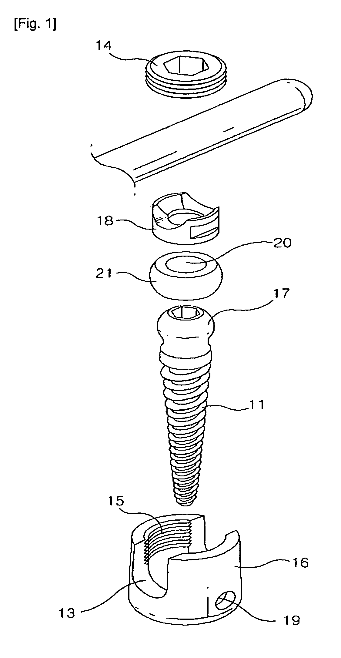
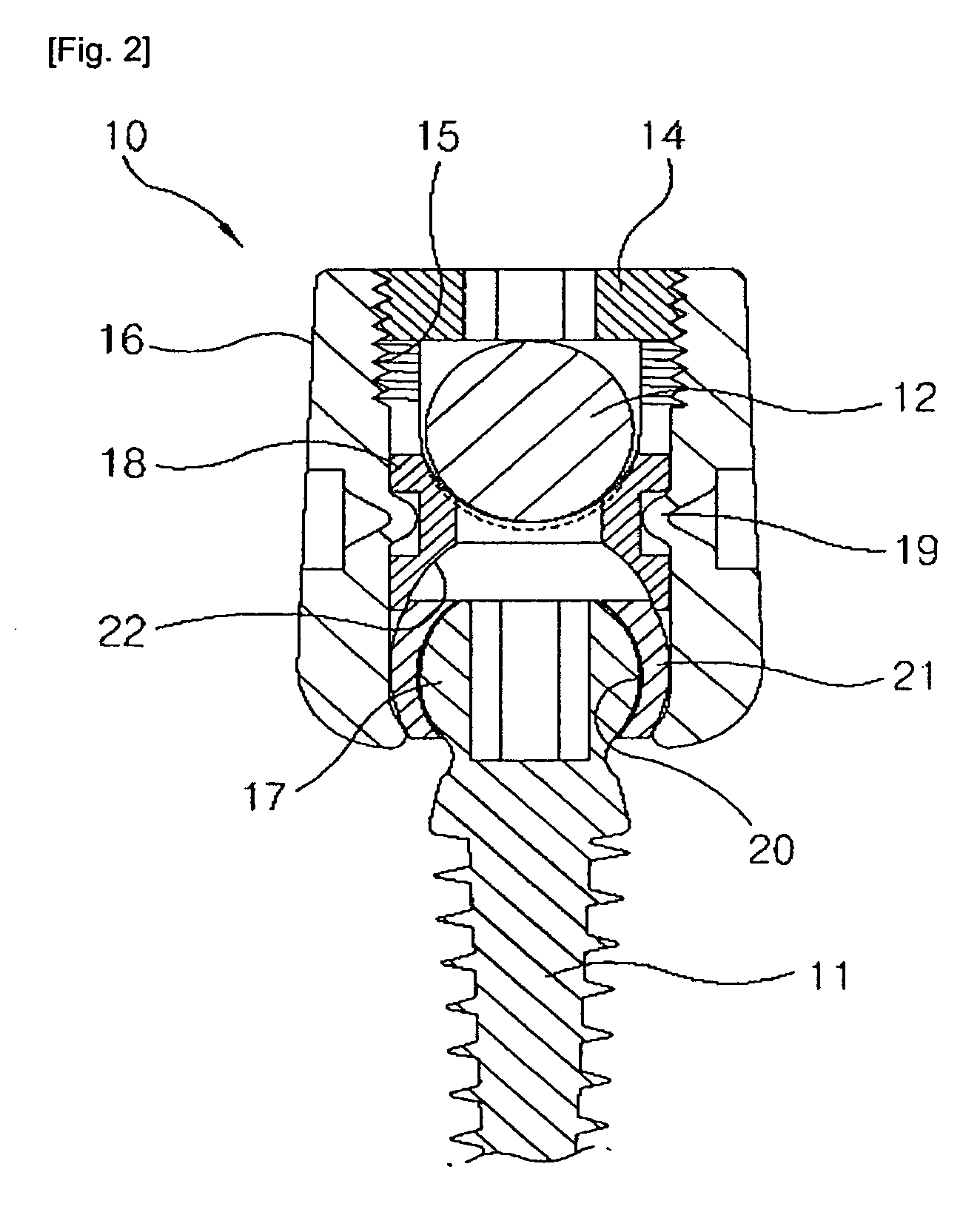
[0026]FIG. 1 is a perspective view illustrating the exploded state of a buffer type vertebral pedicle screw in accordance with an embodiment of the present invention, and FIG. 2 is a sectional view illustrating the assembled state of the buffer type vertebral pedicle screw in accordance with the embodiment of the present invention.

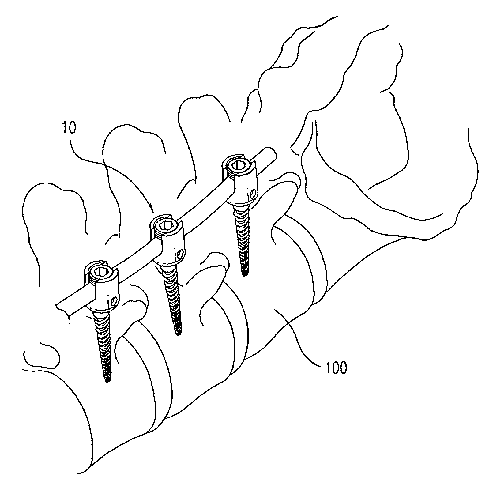
[0027]Referring to FIGS. 1 and 2, a vertebral pedicle screw 10 in accordance with an embodiment of the present invention is made of titanium(Ti) and serves as a medical subsidiary for securely holding a rod connecting vertebral pedicles with one another.

[0028]The vertebral pedicle screw 10 includes a screw body 11 which is driven into each of vertebral pedicles 1...


PUM


Abstract

A vertebral pedicle screw includes a screw body driven into a vertebral pedicle, a housing assembled to an upperend of the screw body and having grooves for seating a rod and a threaded portion for locking a fastening bolt, the fastening bolt pressing the rod positioned thereunder as it is threaded downward, and a fastening ring inserted into the housing. The vertebral pedicle screw further includes an insert placed on an outer surface of a screw head of the screw body in the housing, installed to be partially come into contact with the fastening ring on an upper portion thereof, and accommodating the screw head ofthe screw body on a curved inner surface thereof such that the insert and the screw head are brought into sliding contact with each other, whereby an entire rod-side assembly can be slidingly moved in all directions with respect to the screw body.

Description

TECHNICAL FIELD[0001]The present invention relates to a vertebral pedicle screw used when conducting spine surgery in the field of orthopedics, and more particularly, to a buffer type vertebral pedicle screw which can absorb a shock using a relative sliding characteristic between a screw body driven into a vertebral pedicle and a rod, thereby relieving the pain of a patient and ensuring the stabilization of abody part receiving a surgical operation.BACKGROUND ART[0002]In general, a patient having the damaged spine cannot lead an active life. Even though the patient can be active to some extent due to the lesser degree of the damage to the spine, as the damaged portion of the spine is pressed by or brought into contact withan adjacent portion, a pain is caused to the patient, and a recovery is likely to be retarded.[0003]Therefore, for the patient having the damaged spine, a surgical operationis conducted to support the adjacent portion of the spine using artificial prosthetics so th...

Claims


Application Information

Patent Timeline
24 Sep 2009
Publication
US20090240290A1
IPC
A61B17/86
CPC
A61B17/7037; A61B17/7032; A61B17/74; A61B17/86
Inventors
CHOI, GIL-WOON