Brake control interlock logic

a technology of interlock logic and brake control, applied in the field of brakes, can solve problems such as affecting the operation of brakes, cutting off the flow of power,

Active Publication Date: 2009-09-24
THE BF GOODRICH CO
View PDF3 Cites 18 Cited by
  • Summary
  • Abstract
  • Description
  • Claims
  • Application Information

AI Technical Summary

Benefits of technology

[0008]The validity of the signals can be determined by comparing two independent signals that correspond to pedal deflection (e.g., a first channel providing a first signal corresponding to pedal deflection, and a second channel providing a second signal corresponding to pedal deflection). If the two signals are w

Problems solved by technology

If the signals are determined to be invalid, however, then the brake control device

Method used


Image

  • Brake control interlock logic
  • Brake control interlock logic
  • Brake control interlock logic

Examples


Embodiment Construction

[0027]The principles of the invention will now be described with reference to the drawings. Because the invention was conceived and developed for use in an aircraft braking system, it will be herein described chiefly in this context. However, the principles of the invention in their broader aspects can be adapted to other types of braking systems.

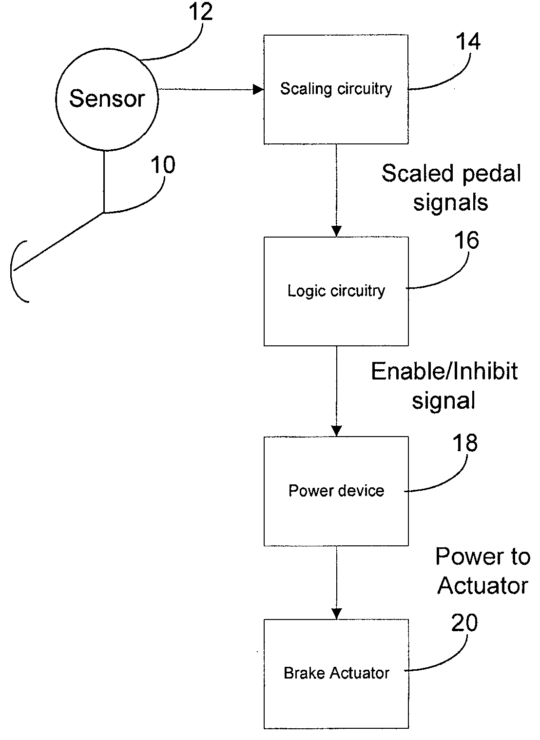
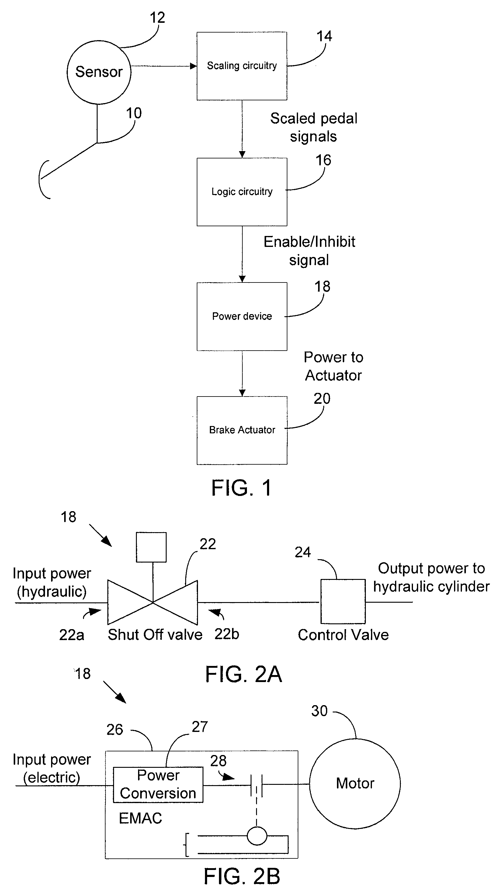
[0028]In braking a vehicle, a brake command is often provided via a brake pedal. More particularly, a requested braking force for a vehicle braking system can be proportional to a deflection of the brake pedal (e.g., increased deflection provides increased braking command to the braking system). The brake command is provided to a brake controller, which controls a braking pressure (and force) applied to the brakes so as to correspond to the brake command.

[0029]As will be appreciated, it is desirable to apply brakes only when commanded to do so. To this end, the brake command generated by the brake pedal should be generated only when a valid...


PUM


Abstract

A brake control circuit for determining if a brake command from a brake pedal is valid is provided. The brake control circuit includes at least two independent channels configured to receive data indicative of brake pedal deflection for the brake pedal, and logic circuitry operatively coupled to the at least two independent channels. The logic circuitry is configured to generate a valid brake flag when the respective channels receive data that are within a predetermined range of one another, and to generate an invalid brake flag when the respective channels receive data that are not within a predetermined range of one another.

Description

RELATED APPLICATION DATA[0001]This application claims priority of U.S. Provisional Application No. 61 / 037,865 filed on Mar. 19, 2008, which is incorporated herein by reference in its entirety.FIELD OF THE INVENTION[0002]The present invention relates generally to brakes and, more particularly, to brake control logic that controls the delivery of hydraulic or electric power in a braking system of a vehicle, such as an aircraft. More particularly, the invention relates to brake logic that prevents untimely, uncommanded actuation of the brakes.BACKGROUND OF THE INVENTION[0003]In hydraulic braking systems for aircraft, the delivery of hydraulic power is controlled via a hydraulic shutoff valve. More particularly, the shutoff valve includes an inlet for receiving pressurized hydraulic fluid, and an outlet for delivering the pressurized hydraulic fluid. The outlet is typically coupled to control valves (e.g., servo valves) that control the actual pressure applied to a brake assembly.[0004]...

Claims


Application Information

Patent Timeline
IPC IPC(8): G06F17/00B60T15/14
CPCB60T8/885B60T17/22B64C25/44B60T2270/413B60T2220/04B60T7/042B60T8/1703B64C25/42
Inventor CAHILL, ERIC D.
Owner THE BF GOODRICH CO
Why Eureka
Try Eureka