Optical fiber drawing methods and drawing furnaces

a drawing method and optical fiber technology, applied in the field of optical fiber drawing methods and drawing furnaces, can solve the problems of increasing the polarization mode dispersion (pmd), the uneven softness of the optical fiber preform, and the increase of the connection loss

Active Publication Date: 2009-10-01
FURUKAWA ELECTRIC CO LTD
View PDF6 Cites 4 Cited by
  • Summary
  • Abstract
  • Description
  • Claims
  • Application Information

AI Technical Summary

Benefits of technology

[0011]According to the present invention, because uneven temperature distribution is reduced in the circumferential direction at a starting point of a meniscus por

Problems solved by technology

The cause of such non-circular optical fiber is unevenness in softness of an optical fiber preform in the circumferential direction due to unevenness of temperature distribution in the heated optical fiber preform, which happens because it is difficult to perfectly match the center axis of a drawing furnace to that of the optical fiber preform.
When an optical fiber has a large non-circularity, it causes problems such as an increase in polarization mode dispersion (PMD) and an increase in connection loss due to misalignment of the cores when the fiber is connected to another optical fiber.
However, even with the methods disclosed in the U.S. Pat. No. 654,760, it is difficult to uniformly distribute the temperature around the circumfere

Method used


Image

  • Optical fiber drawing methods and drawing furnaces
  • Optical fiber drawing methods and drawing furnaces
  • Optical fiber drawing methods and drawing furnaces

Examples


first embodiment

of the Present Invention

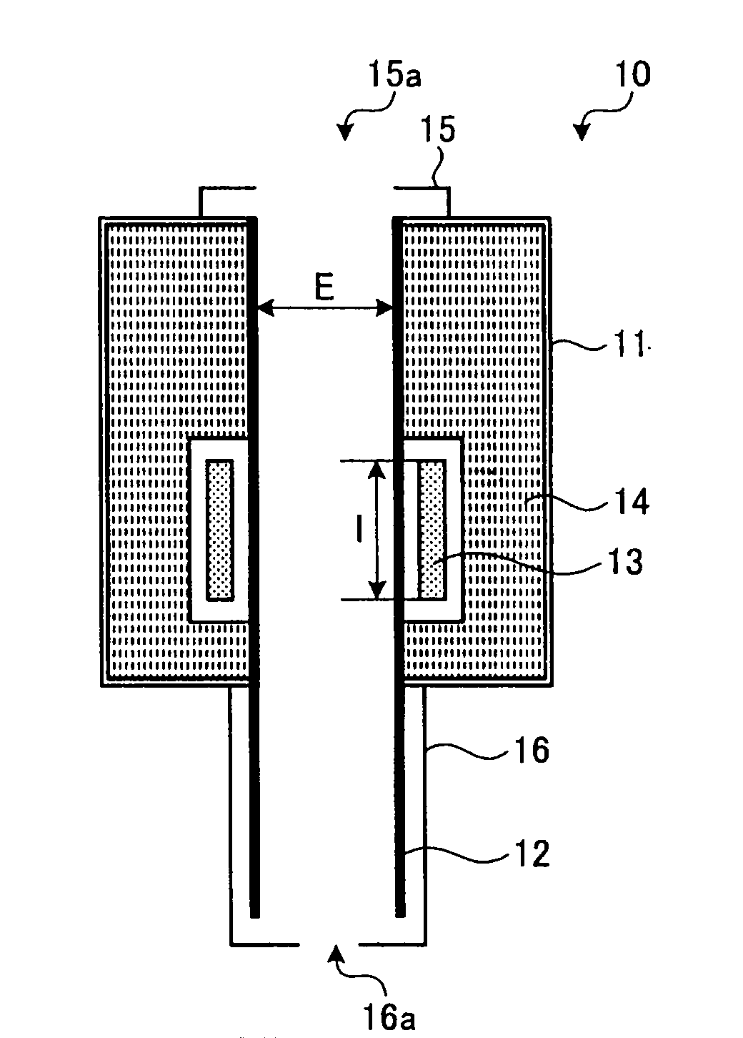
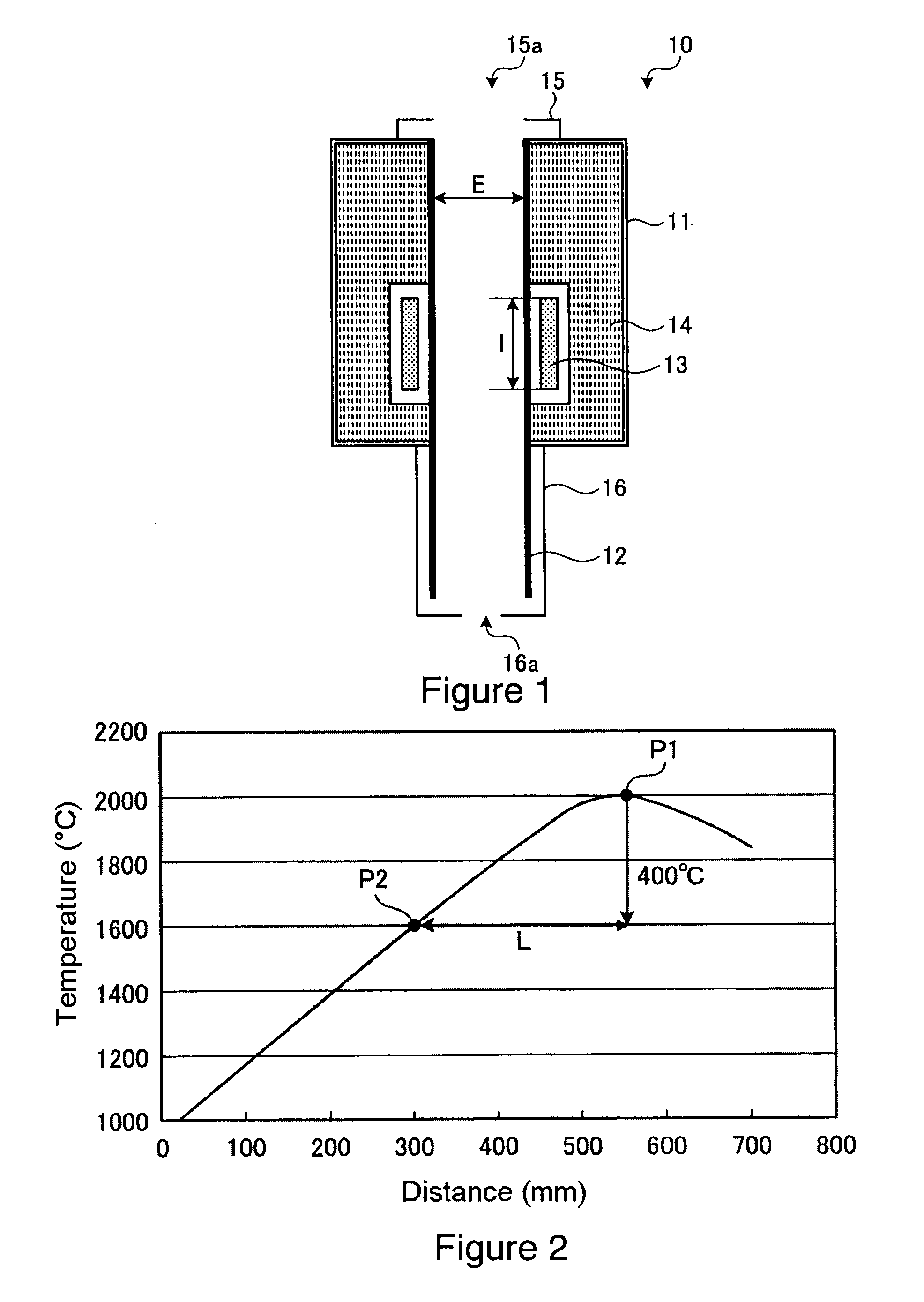
[0022]FIG. 1 is a schematic longitudinal cross section of an optical fiber drawing furnace, which is related to the first embodiment of the present invention. As shown in FIG. 1, the drawing furnace 10 has a furnace body 11, a muffle tube 12, a heater 13 as a primary heater, insulator 14, a top cover 15, and a cooling section 16.

[0023]The furnace body 11 is a cylindrical shape, made from heat-resistant material, and includes the muffle tube 12, the heater 13 and the insulator 14. The muffle tube 12 is a cylindrical shape and made from carbon for example. Also, the heater 13, illustratively a carbon heater, is a cylindrical shape and is placed to cover the muffle tube 12. Also, the insulator 14 is placed around the outside of the muffle tube 12 and the heater 13. The top cover 15 is placed above the furnace body 11. The cooling section 16 is placed under the furnace body 11 and includes the bottom portion of the muffle tube 12. The top cover 15 and the cooling...

example 1

[0031]As an example 1 of the present invention, an optical fiber preform, made from quartz glass, was drawn in a furnace at a drawing tension of 100 gf and a drawing speed of 1,500 m / min. The furnace has the same composition as the first embodiment of the invention, and comprises a muffle tube with an inner diameter E of 150 mm and a heater length I of 250 mm. An optical fiber preform having a diameter D of 125 mm and an average non-circularity (measured every 50 mm in length of the preform) of 0.08% was used. The average non-circularity of the drawn optical fiber (measured every 50 km in length of the fiber) was 0.10%.

example 2

[0032]As an example 2 of the present invention, an optical fiber preform, made from quartz glass, was drawn in a furnace at a drawing tension of 100 gf and a drawing speed of 1,500 m / min. The furnace has the same composition as the first embodiment of the invention, and comprises a muffle tube with an inner diameter E of 180 mm and a heater length I of 350 mm (100 mm longer than the drawing furnace in example 1). An optical fiber preform having a diameter D of 150 mm and an average non-circularity (measured every 50 mm in length of the preform) of 0.07% was used. The average non-circularity of the drawn optical fiber (measured every 50 km in length of the fiber) was 0.10%.


PUM

PropertyMeasurementUnit
Temperatureaaaaaaaaaa
Diameteraaaaaaaaaa
Fractionaaaaaaaaaa

Abstract

Drawing methods and drawing furnaces for drawing an optical fiber with small non-circularity by simple drawing system are provided. An optical fiber preform is received into a muffle tube and heated by a primary heater placed to surround the muffle tube. The optical fiber preform is heated such that a starting position of a meniscus portion is higher in its position than the top of the primary heater, wherein the meniscus portion is created at the bottom portion of the optical fiber preform.

Description

CROSS-REFERENCE TO RELATED APPLICATIONS[0001]This application claims the benefit of priority from Japanese Patent Application No. 2008-083512 filed Mar. 27, 2008, the entire contents of which is incorporated herein by reference.TECHNICAL FIELD[0002]The present invention relates to optical fiber drawing methods and drawing furnaces for drawing an optical fiber from an optical fiber preform.BACKGROUND OF THE INVENTION[0003]An optical fiber is obtained by so-called “drawing”. During draw, the bottom portion of an optical fiber preform is softened by heating, and the tension is applied to the softened portion of the preform to reduce its diameter. The preform is typically made from material such as quartz glass. In general, a drawing system for such a process is equipped with a drawing furnace to heat the optical fiber preform; a cooling device to cool the drawn glass optical fiber; a coating device to coat a resin around the drawn glass optical fiber; and a spooling device to spool the...

Claims


Application Information

Patent Timeline
IPC IPC(8): C03B37/025C03B37/02
CPCC03B37/027C03B37/029C03B2205/40C03B2205/69C03B2205/45C03B2205/63C03B2205/42Y02P40/57
Inventor ORITA, NOBUAKISUZUKI, TAKASHISAKATA, YOSHIYUKI
Owner FURUKAWA ELECTRIC CO LTD
Why Eureka
Try Eureka