
Control method for internal combustion engine system, and internal combustion engine system

a control method and internal combustion engine technology, applied in the direction of engine starters, machines/engines, instruments, etc., can solve the problems of overflow of starter batteries, inability to ensure sufficient electric power during restart of internal combustion engines, and over-current of total electric loads

Inactive Publication Date: 2009-10-01
MAZDA MOTOR CORP
View PDF6 Cites 110 Cited by
  • Summary
  • Abstract
  • Description
  • Claims
  • Application Information

AI Technical Summary

Benefits of technology

[0007]In view of the above problem, it is an object of the present invention to provide an internal combustion engine system control method and an internal combustion engine system, capable of preventing an internal combustion engine in a state after being automatically stopped, from falling into an unrestartable state.
[0009]In cases where a user post-attaches an electric load, e.g., an accessory component, such as a lamp, in such a manner as to use electric power of the starter battery, an amount of electric power stored in the starter battery is likely to reduce in a stopped state of the internal combustion engine. In the control method of the present invention, the presence or absence of such a post-attached load to be supplied with electric power from the starter battery is detected based on a discharging status of the starter battery in the automatically stopped state of the internal combustion engine. Then, when the post-attached load is detected, the internal combustion engine is restarted irrespective of the satisfaction or non-satisfaction of the restart condition. This makes it possible to prevent the automatically stopped internal combustion engine from falling into an unrestartable state.

Problems solved by technology

In such cases, electric power stored in the starter battery is consumed in a stopped state of the internal combustion engine, and thereby the starter battery will fall into an overload state in which a total electric load exceeds an upper limit in design specifications.
The use of the starter battery in the overload state is likely to cause a risk of being unable to ensure sufficient electric power during restart of the internal combustion engine.
However, some recent vehicles employ an electric load requiring electric power supply even in a stopped state of an internal combustion engine, such as a hill start assist system (hill holder), and thereby it is often the case that it is not easy to entirely cover required electric power by the general-purpose battery.

Method used


Image

  • Control method for internal combustion engine system, and internal combustion engine system
  • Control method for internal combustion engine system, and internal combustion engine system
  • Control method for internal combustion engine system, and internal combustion engine system

Examples


first embodiment

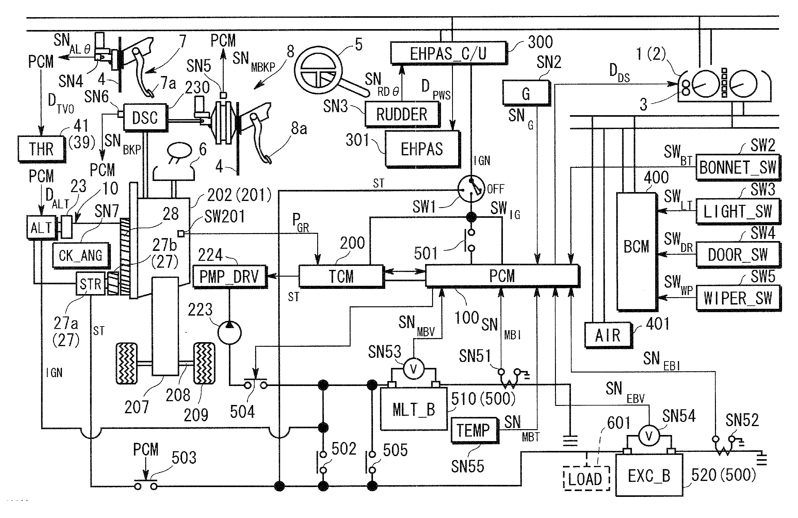
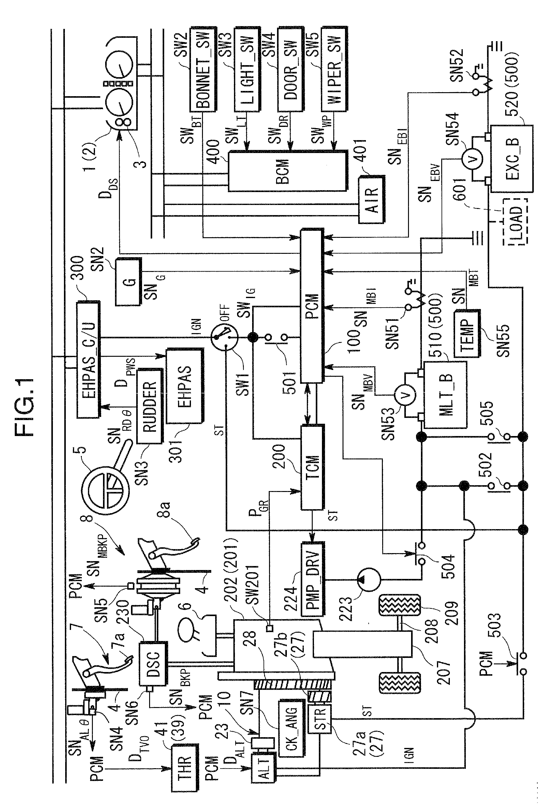
[0023]FIG. 1 is a schematic block diagram showing an internal combustion engine system according to a first embodiment of the present invention.

[0024]Referring to FIG. 1, the internal combustion engine system (a vehicle control system?) comprises a powertrain control module (PCM) 100 operable to control an engine 10 as an internal combustion engine, a transmission control module (TCM) 200 operable to control a transmission 201 coupled to the engine 10 (specifically, the transmission control module 200 is configured as a part of powertrain control module 100), a steering control module (SCM) 300 operable to control a steering unit 301, and a body control module (BCM) 400 operable to control after-mentioned various convenience switches SW2 to SW5 each installed in a vehicle body. Each of the modules 100 to 400 is configured with logic elements. Therefore, practically, two or more of the modules 100 to 400 may be configured in a single integral module, or each of the modules 100 to 400...

second embodiment

[0127]An internal combustion engine system according to a second embodiment of the present invention will be described below.

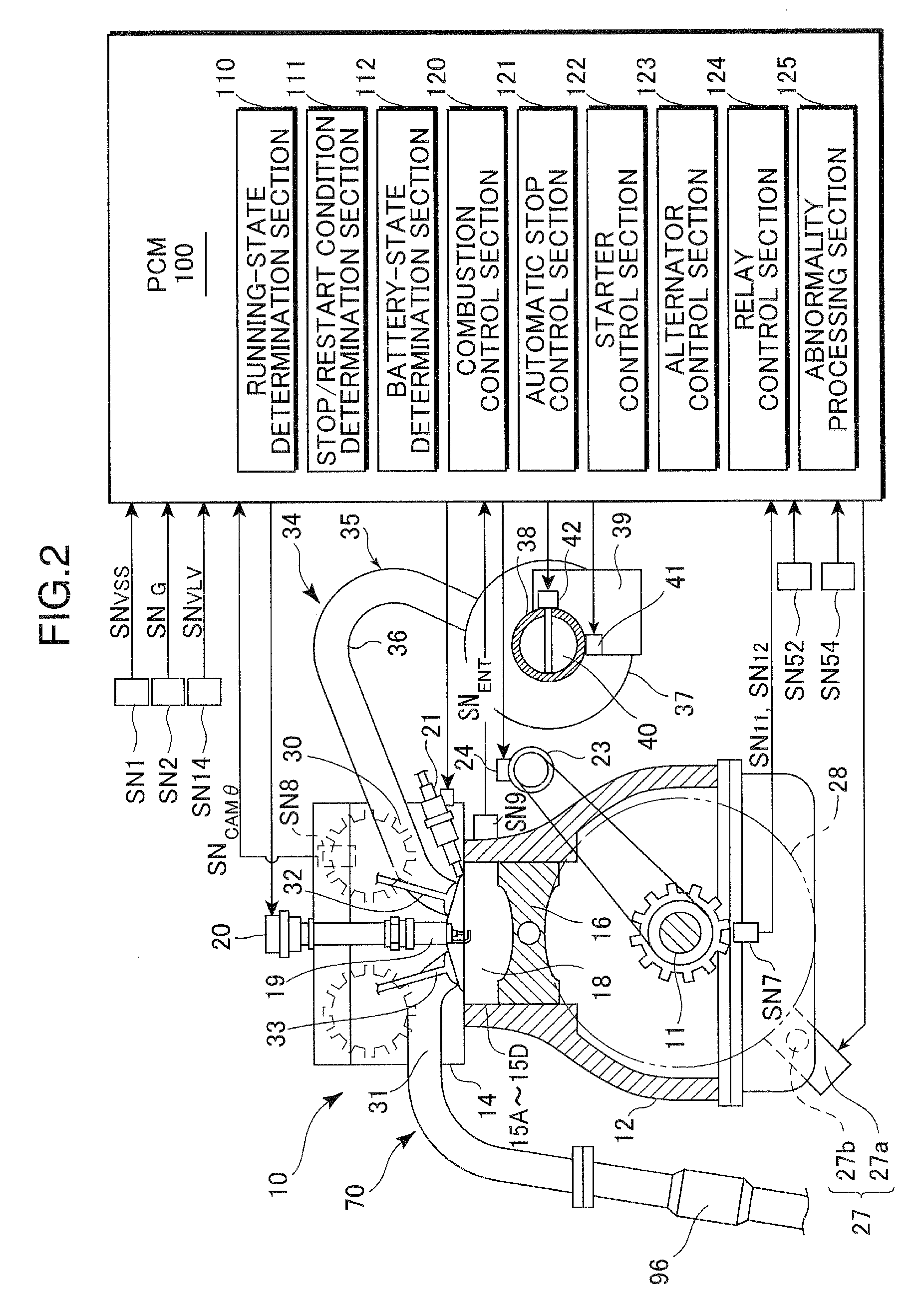
[0128]FIG. 8 is a schematic block diagram showing the internal combustion engine system according to the second embodiment, and FIG. 9 is a schematic block diagram primarily showing an engine in section, in the internal combustion engine system according to the second embodiment.

[0129]Referring to FIGS. 8 and 9, in the second embodiment, a powertrain mounted on a vehicle includes a transmission 201 embodied as a manual transmission, and a passenger compartment of the vehicle is equipped with a clutch pedal 311 of a clutch pedal unit 310 for selectively engaging and disengaging a clutch 204 included in the manual transmission 204.

[0130]FIG. 10 is a schematic block diagram showing respective structures of the manual transmission 201 and the clutch pedal unit 310.

[0131]Referring to FIGS. 8 and 10, the manual transmission 201 comprises a clutch 204 and a gear trai...


PUM


Abstract

The invention relates to a control method for an internal combustion engine system, capable of preventing an internal combustion engine in a state after being automatically stopped, from falling into an unrestartable state. Upon satisfaction of a given automatic stop condition, the engine 10 being running is automatically stopped (Step 11). A value of current IEBAT flowing out of a starter battery 520 is compared with a given current value IEBAT<sub2>—< / sub2>TH, in an automatically stopped state of the engine 10 (Step S30) to diagnosis a discharging status of the starter battery 520. If a result of the diagnosis indicates that the value of current IEBAT flowing out of the starter battery 520 is greater than the given current value IEBAT<sub2>—< / sub2>TH, it is determined that a post-attached load is detected, and the engine 10 is restarted irrespective of the satisfaction or non-satisfaction of a given restart condition.

Description

BACKGROUND OF THE INVENTION[0001]1. Field of the Invention[0002]The present invention relates to an internal combustion engine system control method and an internal combustion engine system, and more particularly to an internal combustion engine system control method and an internal combustion engine system, designed to automatically stop an internal combustion engine, upon satisfaction of a given automatic stop condition, and then automatically restart the internal combustion engine using an electric drive unit.[0003]2. Description of the Background Art[0004]In a control system for an internal combustion engine of a vehicle, there has been known one type designed to, upon satisfaction of a given automatic stop condition (i.e., condition for automatically stopping the internal combustion engine), automatically stop the internal combustion engine, and, upon satisfaction of a given restart condition after the internal combustion engine is automatically stopped, produce combustion of a...

Claims


Application Information

Patent Timeline
IPC IPC(8): F02N17/00F02N99/00
CPCF02N11/0825F02N11/0848F02N11/0866Y02T10/48F02N2200/063F02N2250/06F02N2200/062Y02T10/40
Inventor NAGOSHI, MASAHIROTETSUNO, MASAYUKIYOSHIDA, KATSUMASA
Owner MAZDA MOTOR CORP
Learn More