Photovoltaic Roofing Elements, Laminates, Systems and Kits

a technology of photovoltaic roofs and components, applied in photovoltaic supports, pv power plants, sustainable buildings, etc., can solve the problems of increasing cost of fossil fuels and difficult system design, and achieve the effect of improving the aesthetics of the system and simplifying the electrical interconnection

Inactive Publication Date: 2009-10-01
CERTAINTEED CORP
View PDF19 Cites 48 Cited by
  • Summary
  • Abstract
  • Description
  • Claims
  • Application Information

AI Technical Summary

Benefits of technology

[0028]The photovoltaic roofing elements, laminates, arrays, systems and kits of the present invention can result in a number of advantages. For example, in certain embodiments, the photovoltaic roofing elements and laminates of the present invention can be arranged in a wide variety of geometrical arrangements, with little regard for electrical sy...

Problems solved by technology

First, fossil fuels have become increasingly expensive due to increasing scarcity and unrest in areas rich in petroleum deposits.
Second, there exists overwhelming concern about the effects of th...

Method used


Image

  • Photovoltaic Roofing Elements, Laminates, Systems and Kits
  • Photovoltaic Roofing Elements, Laminates, Systems and Kits
  • Photovoltaic Roofing Elements, Laminates, Systems and Kits

Examples


Embodiment Construction

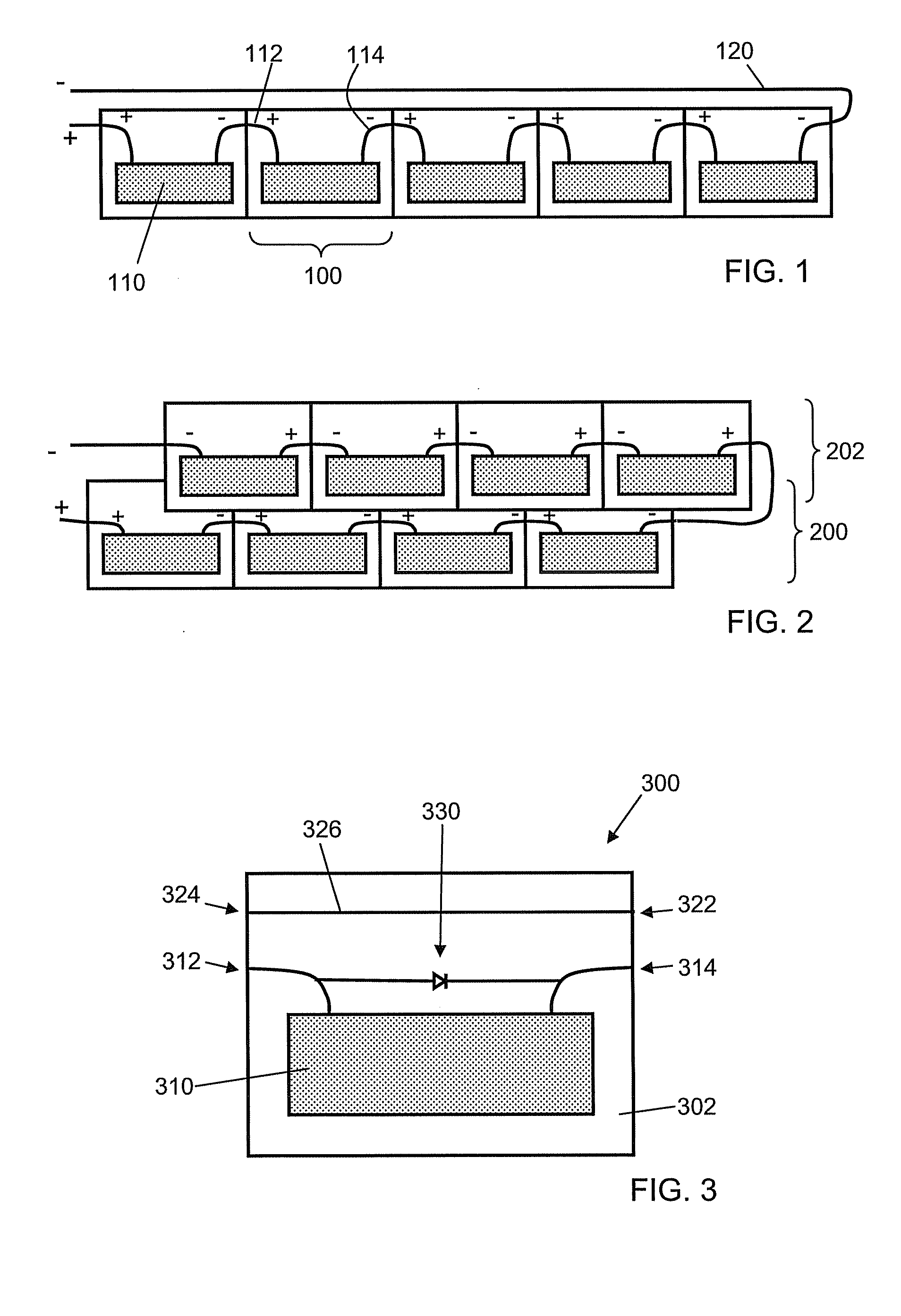
[0039]A comparative example of a series-interconnected plurality of photovoltaic roofing elements is shown in top schematic view in FIG. 1. Photovoltaic roofing elements 100, each bearing photovoltaic elements 110, first (positive) electrical terminus 112 and second (negative) electrical terminus 114 are arranged in a single “course” (i.e., a single horizontal row), and connected in series. Voltage builds up from left to right; a connecting wire 120 is necessary to complete the circuit, so that the series-connected photovoltaic roofing elements can be interconnected into an electrical system, for example a “home run” set of cables (i.e., the parallel backbone of a series-parallel wiring system) that routes the photovoltaically-generated power to an inverter for conversion from direct current to alternating current, or to a direct current powered system for local use.

[0040]In a second comparative example, shown in top schematic view in FIG. 2, two courses of photovoltaic roofing elem...


PUM


Abstract

The present invention relates generally to the photovoltaic generation of electrical energy. The present invention relates more particularly to photovoltaic systems and roofing products for use in photovoltaically generating electrical energy. One aspect of the invention is a photovoltaic roofing element including: a roofing substrate; one or more photovoltaic elements disposed on the roofing substrate; a first electrical terminus and a second electrical terminus, the one or more photovoltaic elements being connected in series between the first electrical terminus and the second electrical terminus; a third electrical terminus and a fourth electrical terminus; and a return electrical path connecting the third electrical terminus to the fourth electrical terminus.

Description

CROSS-REFERENCE TO RELATED APPLICATIONS[0001]This application claims priority under 35 U.S.C. § 119(e) to U.S. Provisional Patent Application Ser. No. 61 / 040,376, filed Mar. 28, 2008, which is hereby incorporated herein by reference in its entirety.BACKGROUND OF THE INVENTION[0002]1. Field of the Invention[0003]The present invention relates generally to the photovoltaic generation of electrical energy. The present invention relates more particularly to photovoltaic systems and roofing products for use in photovoltaically generating electrical energy.[0004]2. Technical Background[0005]The search for alternative sources of energy has been motivated by at least two factors. First, fossil fuels have become increasingly expensive due to increasing scarcity and unrest in areas rich in petroleum deposits. Second, there exists overwhelming concern about the effects of the combustion of fossil fuels on the environment due to factors such as air pollution (from NOx, hydrocarbons and ozone) an...

Claims


Application Information

Patent Timeline
IPC IPC(8): H01L31/048
CPCH01L31/048H02S20/25Y02E10/50Y02B10/12H02S40/34H02S40/36H01L31/044Y02B10/10
Inventor WATTMAN, GEORGE G.DONALDSON, JOHN K.JACOBS, GREGORY F.SHAW, WAYNE E.
Owner CERTAINTEED CORP
Why Eureka
Try Eureka