Systems for inspection of shrouds

a technology of shrouds and inspection systems, which is applied in the direction of resistance/reactance/impedence, instruments, measurement devices, etc., can solve the problems of inability to apply a technique to a gas turbine, inability to release radioactive materials into the environment, and inefficient processes

Inactive Publication Date: 2009-10-01
GENERAL ELECTRIC CO
View PDF16 Cites 21 Cited by
  • Summary
  • Abstract
  • Description
  • Claims
  • Application Information

AI Technical Summary

Problems solved by technology

However, the process is inefficient, time consuming, and costly due to turbine shut down and maintenance.
However, the above techniques can only be applied to steam turbines, which are closed systems, so that radioactive materials in the water stream will not be released to the environment.
The technique cannot be applied to gas turbines because the exhaust is released into the air, and radioactive elements will be detrimental to the environment.
This technique further finds challenges in aircraft engine systems where the sampling and analysis system needs to occur online or during flight, thus increasing the complexity.
Such methods are unable to focus on individual parts since they do not take into account conditions that the parts installed in a particular turbine actually encounter, such as, but not limited to, foreign object damage, variation of operating conditions from site to site, and occasional overfiring of the turbine.

Method used


Image

  • Systems for inspection of shrouds
  • Systems for inspection of shrouds
  • Systems for inspection of shrouds

Examples


Embodiment Construction

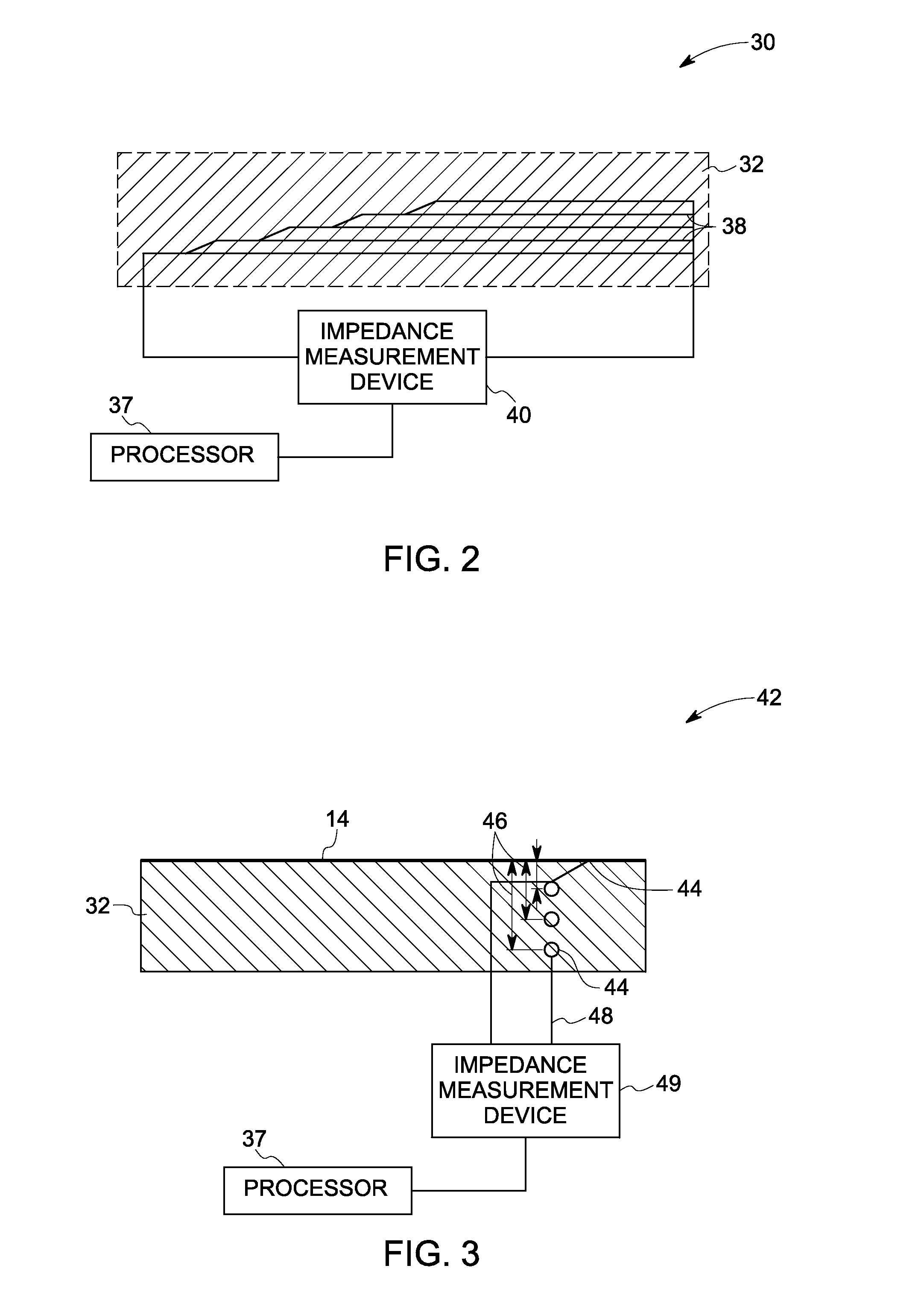
[0021]As discussed in detail below, embodiments of the invention include systems and methods for inspection of a shroud. Embodiments of the invention disclosed herein, assess wear on the shroud by measuring thickness of the shroud. More specifically, a change in resistance of one or more resistive elements embedded within the shroud is measured, which occurs due to wearing out of the shrouds. The wearing of the shroud may occur due to various reasons. A non-limiting example includes wearing away of the shroud due to rubs that occur between a tip of a turbine blade and the shroud.

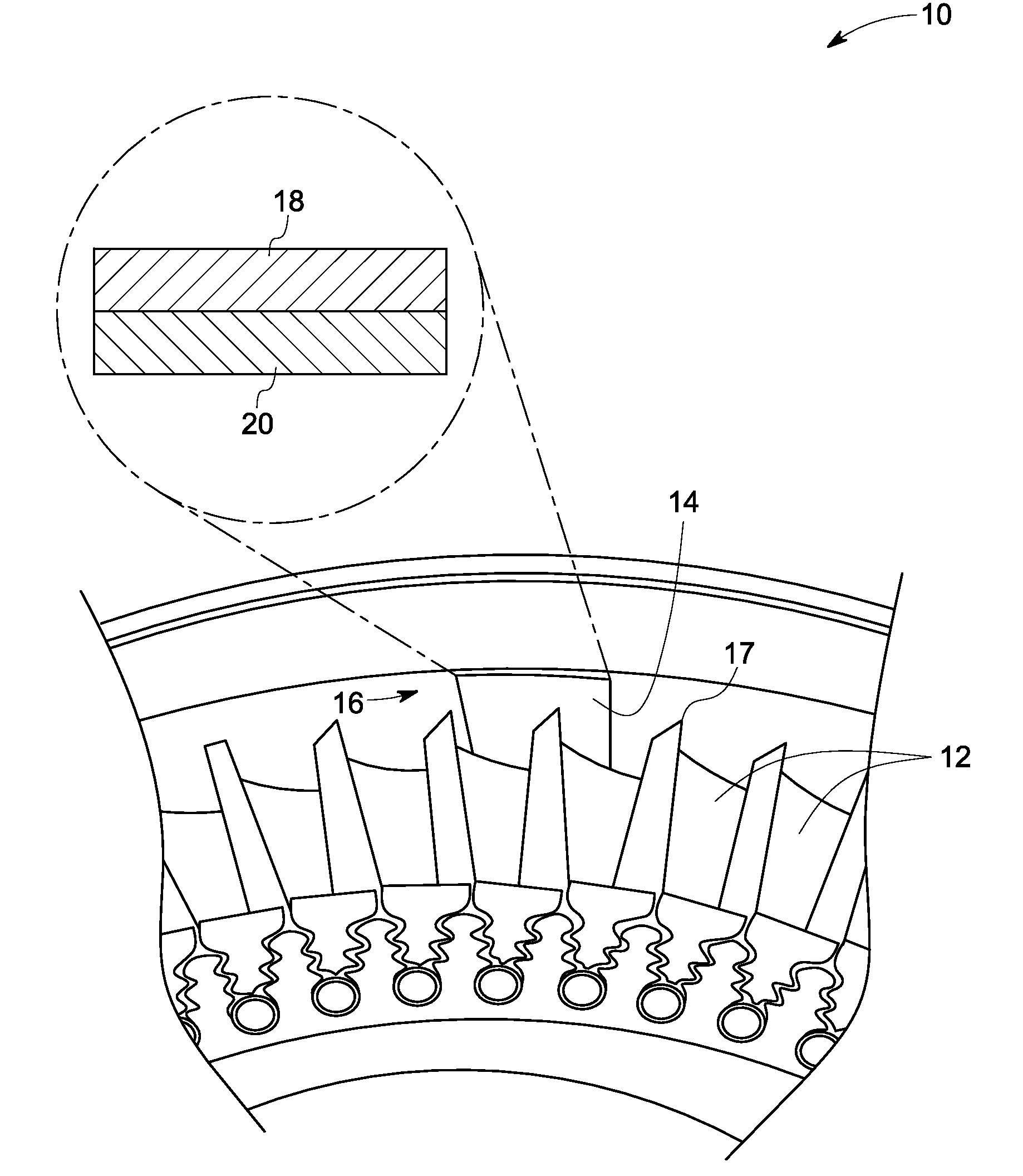
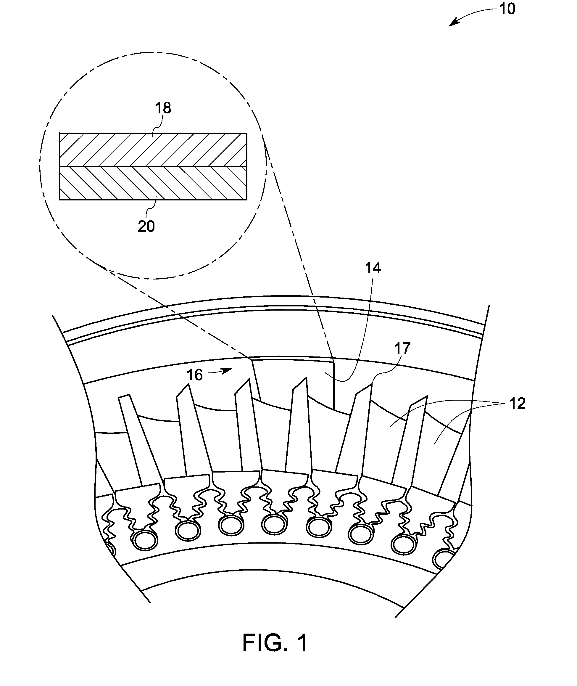
[0022]FIG. 1 is a schematic illustration of a typical turbine blade system 10 including multiple blades 12 and a shroud 14 separated by a clearance 16. A reduction of the clearance 16 may result in rubbing of a tip 17 of the blades 12 against the shroud 14. Such an interaction may be tolerated by providing an abradable coating layer 18 deposited upon a thermal barrier coating layer 20. The abradable coating ...


PUM

PropertyMeasurementUnit
diameteraaaaaaaaaa
thicknessaaaaaaaaaa
diameteraaaaaaaaaa

Abstract

A system to measure thickness of a shroud is provided. The system includes at least one resistive element embedded within the shroud. The system also includes an impedance measurement device that measures a total resistance associated with the at least one resistive element.

Description

BACKGROUND[0001]The invention relates generally to systems and methods for assessing wear or damage to turbine parts and more specifically, to wear in a shroud of the turbine.[0002]There are several techniques that are currently used for inspection of turbine parts. A commonly used technique includes schedule-based shutting down of a turbine and physically examining parts at predetermined intervals. However, the process is inefficient, time consuming, and costly due to turbine shut down and maintenance. Further, several on-line methods have been developed for detecting wear-out of turbine parts such as, but not limited to, shrouds.[0003]For example, Blatchley and coworkers (C. C. Blatchley and R. J. Bricault Jr., in Tribological Mechanisms & Wear Problems in Materials, ASM International, Metals Park, Ohio, 1987, pp. 95-100 and C. C. Blatchley and P. G. Loges, in Advances in Steam Turbine Technology for Power Generation, ASME, New York, N.Y., 1990, Vol. 10, pp. 9-13) developed a “sur...

Claims


Application Information

Patent Timeline
Patent Type & Authority Applications(United States)
IPC IPC(8): G01N27/04G01R27/00
CPCG01N27/041
Inventor ANDARAWIS, EMAD ANDARAWISUMEH, CHUKWUELOKA OBIORA
Owner GENERAL ELECTRIC CO
Why Eureka
Try Eureka