Antenna for compact satellite terminal

Active Publication Date: 2009-10-01
THE UNITED STATES OF AMERICA AS REPRESETNED BY THE SEC OF THE AIR FORCE
View PDF3 Cites 39 Cited by
  • Summary
  • Abstract
  • Description
  • Claims
  • Application Information

AI Technical Summary

Benefits of technology

[0023]An additional object of the present invention is to overcome a lack in the prior art of portable satellite antenna designs, some of which are compact but offer neither true parabolic characteristics nor ruggedness.
[0024]Briefly stated, the present invention achieves these and other objects by providing an antenna for a compact satellite terminal. The antenna is a rigid parabolic structure of metal matrix composite capable of disassembly into segments

Problems solved by technology

The problem not solved by Nonaka is reducing the transportable size of the parabolic antenna reflector.
The problem with this approach is that the triangular and rectangular sections, when not deployed, are positioned perpendicularly to the main reflector, resulting in the overall displaced volume of the antenna structure to be as great when stowed as when deployed.
One limitation of this approach is that phased antennas yield optimum radiation patterns at the specific frequency their reactive elements are designed for, whereas parabolic refle

Method used


Image

  • Antenna for compact satellite terminal
  • Antenna for compact satellite terminal
  • Antenna for compact satellite terminal

Examples


Embodiment Construction

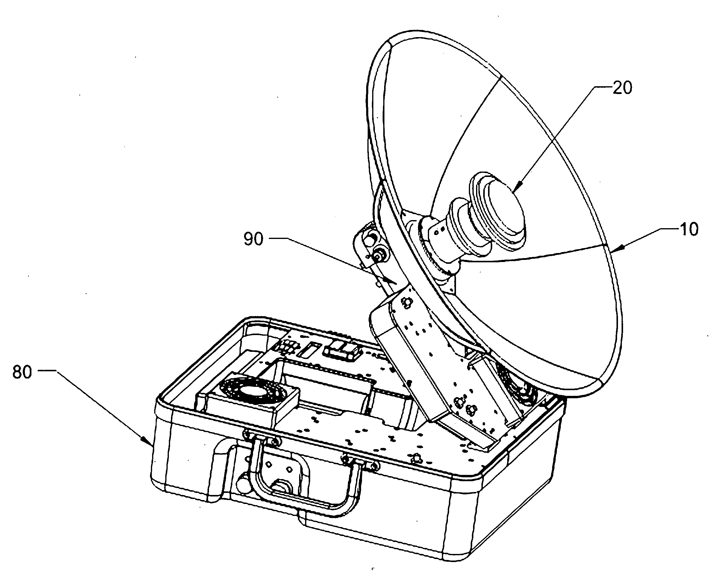
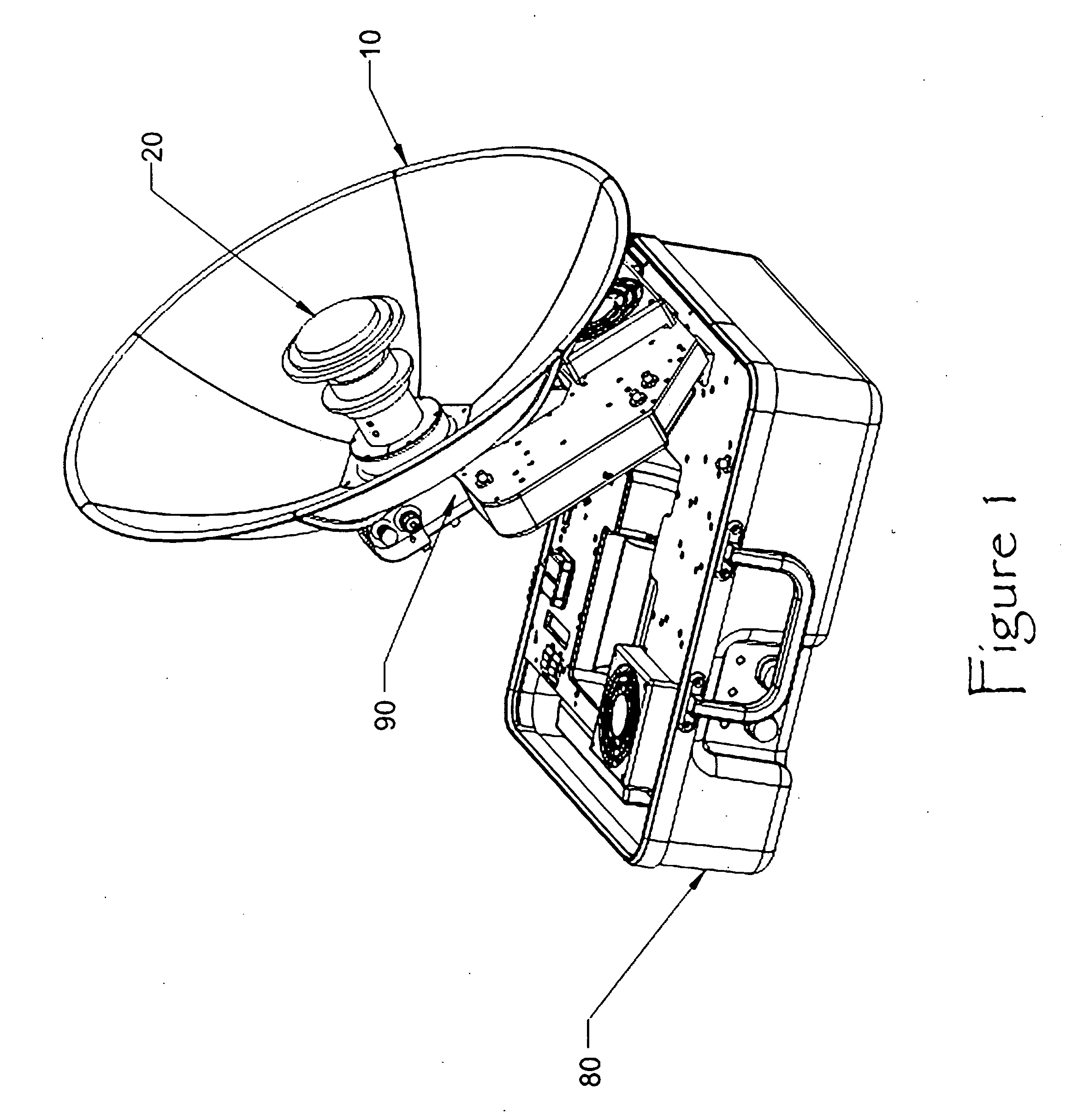
[0037]The present invention describes an antenna design that collapses into an optimally-dense package for stowage and carrying, and which can be easily set up and taken down. Such an antenna would find application in very compact and highly portable satellite communications terminals. The invention incorporates a number of unique features which collectively result in a very lightweight and compact system which can be configured to support full-duplex communications over satellites in earth orbit. These satellites are in most cases envisioned to be in geosynchronous orbit, with the satellite terminal antenna in a fixed orientation during the communications session. However, transportable terminal designs should be readily modifiable to provide for active tracking of the antenna for use on a moving platform, or with non geosynchronous satellites. Those skilled in the art would appreciate a practical implementation of the invention as readily applicable to a backpack transportable sys...


PUM


Abstract

An antenna for a compact satellite terminal. Antenna is a rigid parabolic structure of metal matrix composite capable of disassembly into segments affording a high degree of portability such as for man-packable satellite terminals and the like. A shallow feed horn assembly is joined to an orthomode transducer by a common hub, the hub also serving as the attachment point for a plurality of antenna segments, where a quick release means joins the segments to the hub. The feed horn, hub, orthomode transducer and antenna segments are designed for extremely compact stowability in a variety of applications.

Description

PRIORITY CLAIM UNDER 35 U.S.C. §119(e)[0001]This patent application claims the priority benefit of the filing date of provisional application Ser. No. 61 / 123,565, having been filed in the United States Patent and Trademark Office on Mar. 25, 2008 and now incorporated by reference herein.STATEMENT OF GOVERNMENT INTEREST[0002]The invention described herein may be manufactured and used by or for the Government of the United States of America for governmental purposes without the payment of any royalty thereon.BACKGROUND OF THE INVENTION[0003]1. Technical Field of the Invention[0004]This invention relates generally to the field of ground-based satellite communications equipment. More specifically the present invention relates to lightweight, portable, ground satellite communications terminals and stowable antenna structures to be used therewith.[0005]2. Background[0006]Communication by satellite is essential in remote locations of the world where terrestrial communications networks do n...

Claims


Application Information

Patent Timeline
IPC IPC(8): H01Q1/08H01Q1/12
CPCH01Q1/08H01Q15/162H01Q15/161H01Q1/12
Inventor LEGARE, DAVID J.HUMMEL, DAVID M.
Owner THE UNITED STATES OF AMERICA AS REPRESETNED BY THE SEC OF THE AIR FORCE
Why Eureka
Try Eureka