Printing Device, Print Control Device, and Printing Method

a printing device and control device technology, applied in printing, other printing apparatus, etc., can solve the problems of dulled image formed by color ink, difficult to sufficiently utilize the characteristics of metallic ink,

Inactive Publication Date: 2009-10-01
SEIKO EPSON CORP
View PDF4 Cites 22 Cited by
  • Summary
  • Abstract
  • Description
  • Claims
  • Application Information

AI Technical Summary

Benefits of technology

[0007]An advantage of some aspects of the invention is that printing capable of solving the above-described problems is realized.

Problems solved by technology

However, in the ink jet printer, since the sizes of ejected ink droplets are small, an image formed by a color ink is dulled in a region in which both the metallic ink and the colo

Method used


Image

  • Printing Device, Print Control Device, and Printing Method
  • Printing Device, Print Control Device, and Printing Method
  • Printing Device, Print Control Device, and Printing Method

Examples


first example

C.

(C1) Printing Process of First Example:

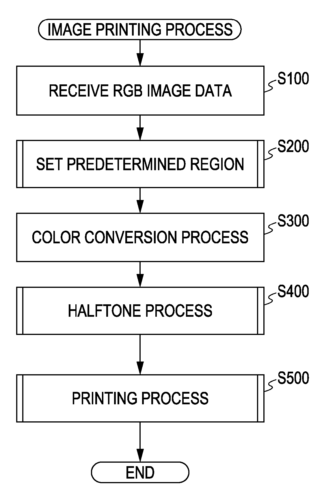
[0064]FIG. 4 is a flowchart showing an image printing process according to a first example of the invention. This image printing process is performed by allowing the CPU 102 to execute a prepared program by the printer driver 24 in hardware. When the process of FIG. 4 is started, the printer driver first receives input image data of an RGB format from the application program (step S100). After the image data is received, the printer driver 24 performs a process of setting a predetermined region, in which printing using the metallic ink is performed, using the specific region extraction module 40 (step S200). The predetermined region may be set by various methods, and, among them, for example, as shown in FIG. 5A, a process of extracting a region other than a skin color region and imparting a mark to that region may be used. In the process of extracting the region other than the skin color region, the computer 100 converts a color space of the...

first modified example

(C2)

[0086]Although a combination of FIGS. 7 and 8 is used as the dot recording ratio table in the above-described first example, a table T11 shown in FIG. 12 may be used as the dot recording ratio table used in the region using the metallic ink. In this table T11, with respect to the image data, the recording ratio S of the small dot is 0 and the recording ratio M of the intermediate dot is set such that the intermediate dot is formed from a range in which the image data is small. The recording ratio L of the large dot is set such that the large dot is formed in a range in which the image data is smaller than that of the table T2 shown in FIG. 8 (a range in which a gradation value is low). As a result, in the region using the metallic ink, the small dot is not formed and only the intermediate dot and the large dot are formed. Accordingly, it is possible to further suppress the generation of the dullness of the color ink due to the scattering of the light, compared with the first exa...

second modified example

(C3)

[0087]Although the color ink is ejected on the metallic ink in the first example, as shown in FIG. 13, even in the region using the metallic ink, the color ink may be ejected in the region in which the printing using the metallic ink is not performed. Even in this case, in the region using the metallic ink, the color ink is formed by a relatively large dot such that the scattering of the light is suppressed and the dullness of the color in the region using the metallic ink is suppressed.


PUM


Abstract

Provided is a printing device which prints an image using a metallic ink and a color ink, the device including: a recording unit which records the metallic ink and the color ink on a printing medium; an input unit which inputs image data; a metallic ink region specifying unit which specifies a region using the metallic ink, in the formation of the image according to the input image data; and a print control unit which prints the image while the color ink is formed relatively larger than that of a region without using the metallic ink, in the region using the metallic ink.

Description

[0001]This application is based upon and claims the benefit of priority from the prior Japanese Patent Applications No. 2008-079713, filed on Mar. 26, 2008, the entire content of which is incorporated herein by reference.BACKGROUND[0002]1. Technical Field[0003]The present invention relates to a technology of printing an image using a metallic ink and a color ink. In the present specification, an ink includes a toner, which is attached to a latent image formed on a photosensitive drum and is transferred, or a coloring material transferred from an ink ribbon to a sheet by a process such as thermal fusion, or a dye-based ink in which a dye is melted in a solvent, or a pigment-based ink in which a pigment is dispersed in a solvent.[0004]2. Related Art[0005]In an electrophotographic field, a technology of printing an image using both a process color toner and a metallic toner with respect to a portion of image data to be printed, in which a metallic color is specified, and printing an im...

Claims


Application Information

Patent Timeline
IPC IPC(8): B41J29/38
CPCB41J2/2107
Inventor KAKUTANI, TOSHIAKI
Owner SEIKO EPSON CORP
Why Eureka
Try Eureka