
Printing apparatus, target transport device, and target transport method

a technology of target transport and printing apparatus, which is applied in the direction of printing and other printing apparatus, etc., can solve the problems of insufficient heating of printing sheets and spread of ink

Inactive Publication Date: 2009-10-01
SEIKO EPSON CORP
View PDF2 Cites 4 Cited by
  • Summary
  • Abstract
  • Description
  • Claims
  • Application Information

AI Technical Summary

Benefits of technology

[0009]An advantage of some aspects of the invention is to provide a printing apparatus, a target transport device, and a target transport method, in which temperature of a surface of a transport belt supporting a target can be desirably distributed at the time of transporting the target using the transport belt.
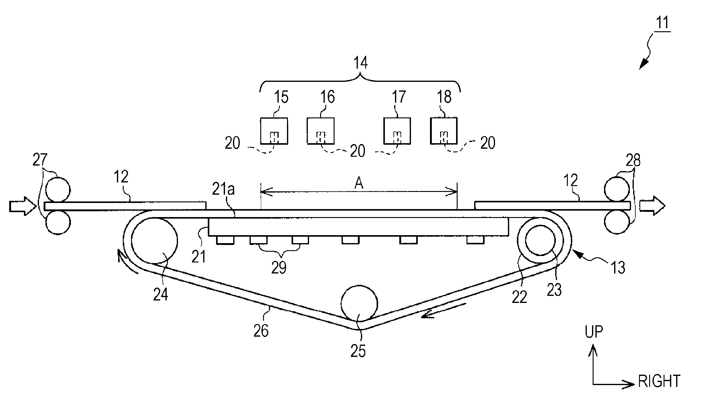
[0014]Generally, when heat is applied from the heating unit to the transport belt through the support member, heat of the surface of the support member supporting the target is transferred from the upstream side to the downstream side in the transport direction of the target by the movement of the transport belt at the time of transporting the target using the transport belt. For this reason, on the surface of the support member supporting the target, temperature of the downstream side in the transport direction of the target becomes higher than that of the upstream side. Accordingly, also on the surface of the transport belt supporting the target, temperature of the downstream side of in the transport direction of the target becomes higher than that of the upstream side. That is, a difference in temperature occurs on the surface of the transport belt supporting the target at the time of transporting the target using the transport belt. About this point, according to the above-described configuration, heat is applied from the heating unit to the support member so that an amount of heat applied from the heating unit to an upstream half of the support member in the transport direction of the target is larger than an amount of heat applied from the heating unit to a downstream half of the support member in the transport direction of the target. Therefore, it is possible to suppress the difference in temperature on the surface of the transport belt supporting the target at the time of transporting the target using the transport belt.
[0016]Generally, when heat is applied from the heating unit to the transport belt through the support member, the amount of heat transferred from the upstream side to the downstream side in the transport direction of the target by the transport belt becomes larger on the surface of the support member supporting the target as a transport speed of the target transported by the transport belt becomes higher. That is, a different in temperature between the upstream side and the downstream side in the transport direction of the target becomes larger as a driving speed of the transport belt driven by the driving unit becomes higher. About this point, according to the invention, the heating unit and the driving unit are controlled by the control unit so that the amount of heat applied from the heating unit to the upstream half of the support member in the transport direction of the target becomes larger than the amount of heat applied from the heating unit to the downstream half of the support member in the transport direction of the target as the transport speed of the target transported by the transport belt becomes higher. For this reason, even when the transport speed of the target transported by the transport belt is changed at the time of transporting the target using the transport belt, the amounts of heat applied from the heating unit to the upstream half and the downstream half of the support member in the transport direction of the target are controlled, thereby reducing the difference in temperature between the upstream side and the downstream side of the transport belt in the transport direction of the target. That is, it is possible to suppress the difference in temperature on the surface of the transport belt supporting the target at the time of transporting the target using the transport belt.
[0018]With such a configuration, the difference in temperature of the surface of the transport belt supporting the target is suppressed, thereby warming the target uniformly. Accordingly, it is possible to dry and fix liquid attached to the printing-processed target without irregularity.
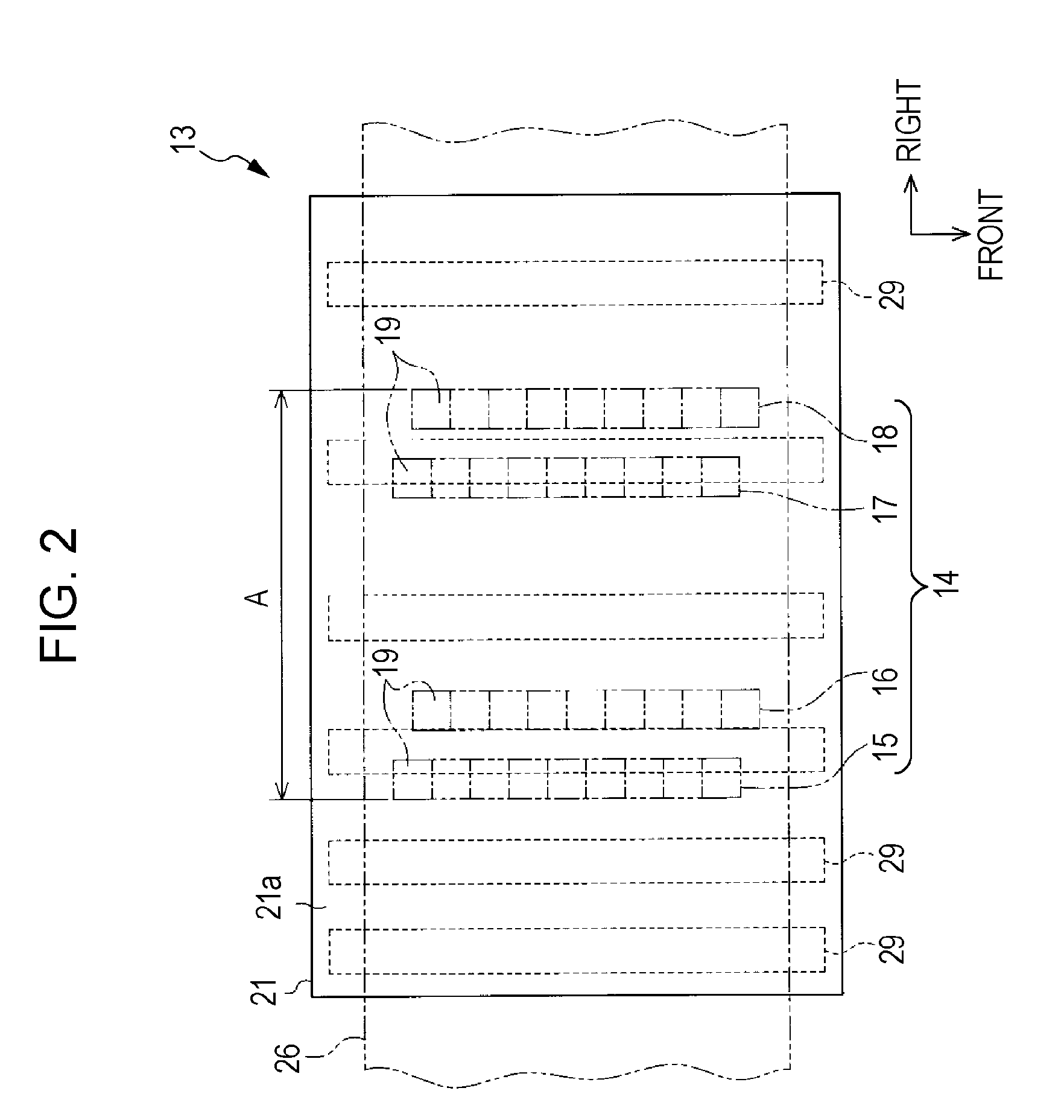
[0019]In the printing apparatus, it is preferable that the heat applying unit applies heat from the heating unit to the support member at the time of transporting the target using the transport belt so as to suppress a difference in temperature of an area corresponding to at least a range from a printing process start position to a printing process end position of the printing unit on a surface of the transport belt supporting the target in a transport direction of the target.
[0020]With such a configuration, it is possible to warm the target substantially uniformly, at least while the printing process is performed on the target. Accordingly, it is possible to reliably dry and fix liquid attached to the target in the course of the printing process without irregularity.

Problems solved by technology

Thus, the printing sheet is not sufficiently heated, and the ink may spread and cohere.

Method used


Image

  • Printing apparatus, target transport device, and target transport method
  • Printing apparatus, target transport device, and target transport method
  • Printing apparatus, target transport device, and target transport method

Examples


modified example

[0057]The embodiment may be modified as follows.

[0058]As shown in FIG. 4, the six heaters 29 may be modified into one rectangular sheet-shaped heater 31 attached to cover the substantially whole lower surface of the platen 21, and a patterning process may be performed so that density of a heating wire 31a of the heater 31 becomes gradually lower from the left side toward the right side of the platen 21. With such a configuration, it is possible to reduce the number of components, and it is possible to apply heat to the platen 21 so that the temperature of the support surface 21a of the platen becomes gradually lower from the left side to the right side in the stationary state of the transport belt 26. In this case, the heater 31 may be embedded in the platen 21.

[0059]As shown in FIG. 5 and FIG. 6, a plurality (9 in this example) of heaters 29 are arranged with the same interval in the left-right direction, and there are provided a left temperature sensor 32 and a right temperature s...


PUM


Abstract

A target transport device includes a transport belt that transports a target from an upstream side to a downstream side, a support member that supports the target transported by the transport belt over the transport belt, a heating unit that heats the support member, and a heat applying unit that applies heat from the heating unit to the support member so that a difference in temperature occurs on a surface of the supporting member supporting the target in a transport direction of the target.

Description

BACKGROUND[0001]1. Technical Field[0002]The present invention relates to a printing apparatus such as an ink jet printer, a target transport device provided in the printing apparatus, and a target transport method in the printing apparatus.[0003]2. Related Art[0004]In related art, a serial type ink jet printer has been known as a kind of a printing apparatus performing a printing process on a target. In such a printer, ink is ejected onto a printing medium (target) transported on a platen (support member), from a plurality of nozzles of a printing head (printing unit) mounted on a carriage reciprocating in a direction perpendicular to a transport direction of the printing medium, thereby performing a printing operation. In the printer, the platen supporting the printing medium is heated uniformly by a heater (heating unit) to uniformly fix the ink, which is ejected from the printing head and attached onto the printing medium, to the printing medium.[0005]In addition to the serial ty...

Claims


Application Information

Patent Timeline
IPC IPC(8): B41J2/01
CPCB41J11/002B41J13/0027B41J11/007B41J11/00242B41J11/00244
Inventor HABA, SHINJI
Owner SEIKO EPSON CORP
Learn More