
Ultra small core fiber with dispersion tailoring

a technology of small core fibers and tailoring, applied in the field of optical fibers, can solve the problems of large air hole size, large number of air holes, and loss of confinemen

Inactive Publication Date: 2009-10-01
IMRA AMERICA
View PDF12 Cites 19 Cited by
  • Summary
  • Abstract
  • Description
  • Claims
  • Application Information

AI Technical Summary

Benefits of technology

[0009]Various embodiments of optical fiber designs and fabrication techniques for fibers such as USCFs with low splice loss, tailored dispersion, and / or low scattering loss are provided.

Problems solved by technology

A significant drawback of this design is the need to use a large number of air holes beyond the inner layer of air holes to reduce confinement loss, especially for core diameters less than 2 μm.
The need for low confinement loss leads to the large air hole size (relative to the hole spacing) and the large number of air holes.
The need for low confinement loss makes dispersion tailoring very difficult for a fixed core diameter.

Method used


Image

  • Ultra small core fiber with dispersion tailoring
  • Ultra small core fiber with dispersion tailoring
  • Ultra small core fiber with dispersion tailoring

Examples


Embodiment Construction

[0035]In the following detailed description, reference is made to “filling fraction,” also known as “void-filling fraction” or “air-filling” fraction. In certain embodiments, the filling fraction refers to a cross-sectional area occupied by certain features in a region (such as, e.g., air holes in a cladding) divided by a total cross-sectional area of the region. The term filing factor is also used herein synonymously with filling fraction.

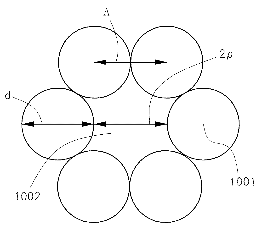
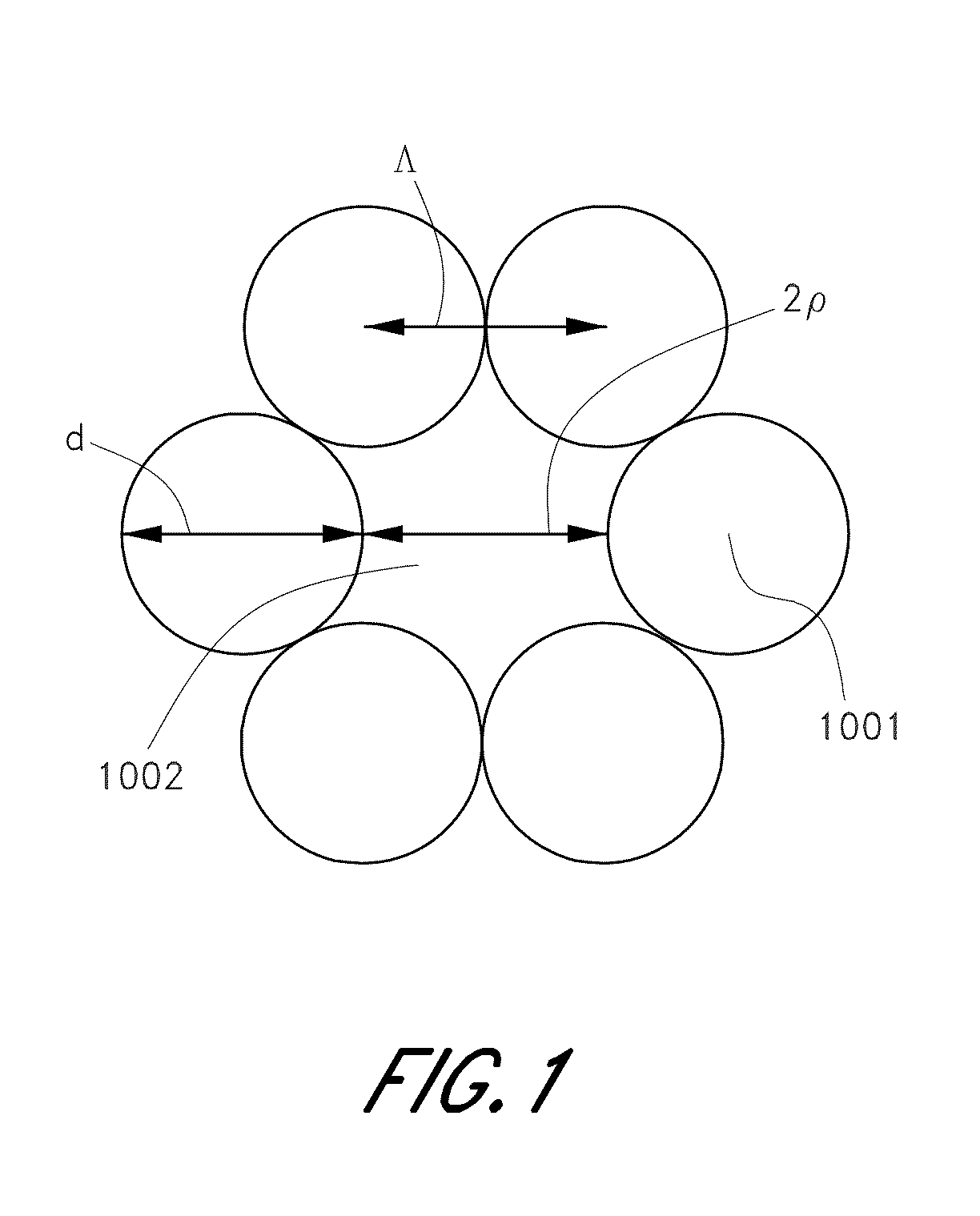
[0036]In certain such embodiments, the filling fraction may be determined for periodic features in the region, where, for example, a basic unit cell is repeated to fill the region. One possible expression for the filling fraction for circular features having a diameter d and center-to-center spacing (pitch) Λ in an infinite triangular matrix was disclosed in U.S. Pat. No. 6,444,133, entitled “Method of Making Photonic Bandgap Fibers” as the following formula:

FillingFraction=π23(dΛ)2

[0037]This formula for the filling fraction may be applied to, for...


PUM

PropertyMeasurementUnit
transverse widthaaaaaaaaaa
diameteraaaaaaaaaa

Abstract

Various embodiments of optical fiber designs and fabrication processes for ultra small core fibers (USCF) are disclosed. In some embodiments, the USCF includes a core that is at least partially surrounded by a region comprising first features. The USCF further includes a second region at least partially surrounding the first region. The second region includes second features. In an embodiment, the first features are smaller than the second features, and the second features have a filling fraction greater than about 90 percent. The first features and / or the second features may include air holes. Embodiments of the USCF may provide dispersion tailoring. Embodiments of the USCF may be used with nonlinear optical devices configured to provide, for example, a frequency comb or a supercontinuum.

Description

CROSS REFERENCE TO RELATED APPLICATIONS[0001]The present application claims priority to U.S. Provisional Patent Application No. 61 / 039,717, filed Mar. 26, 2008, entitled “ULTRA SMALL CORE FIBER WITH DISPERSION TAILORING,” the entirety of which is hereby incorporated by reference herein.BACKGROUND[0002]1. Field[0003]Embodiments disclosed herein relate generally to optical fibers and more particularly to ultra small core fibers.[0004]2. Description of the Related Art[0005]Ultra small core fibers (“USCFs”) have a variety of applications especially in devices that utilize optical nonlinearities. Ultra small core fibers have been used for supercontinuum generation, wavelength conversion, soliton-based pulse compression, and so forth.[0006]U.S. Pat. No. 6,792,188 discloses a design where an inner layer of small holes is used to achieve tailored dispersion of a photonic crystal fiber. In this disclosure, a large number of air holes are used beyond the inner layer of small air holes. A sign...

Claims


Application Information

Patent Timeline
Patent Type & Authority Applications(United States)
IPC IPC(8): G02B6/032G02B6/42
CPCC03B37/0122G02F1/395C03B2201/86C03B2203/10C03B2203/14C03B2203/42C03B2205/08C03B2205/10G02B6/02214G02B6/02333G02B6/02357H01S3/0057H01S3/06729H01S3/06754G02F1/365C03B2201/82
Inventor DONG, LIANGTHOMAS, BRIANFU, LIBIN
Owner IMRA AMERICA
Learn More