Optical fibre and optical fibre device
a technology of optical fibre and optical fiber device, applied in the field of optical fibre, can solve the problems of increased bend loss, adverse changes, and change from single mode optical fibr
- Summary
- Abstract
- Description
- Claims
- Application Information
AI Technical Summary
Benefits of technology
Problems solved by technology
Method used
Image
Examples
example 1
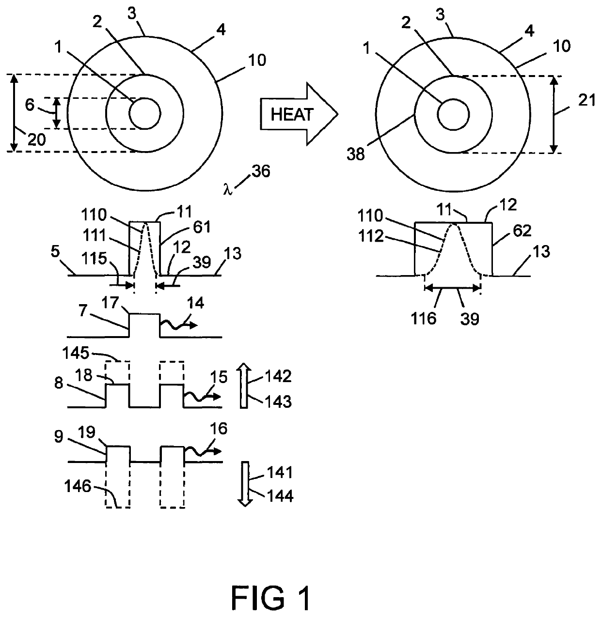
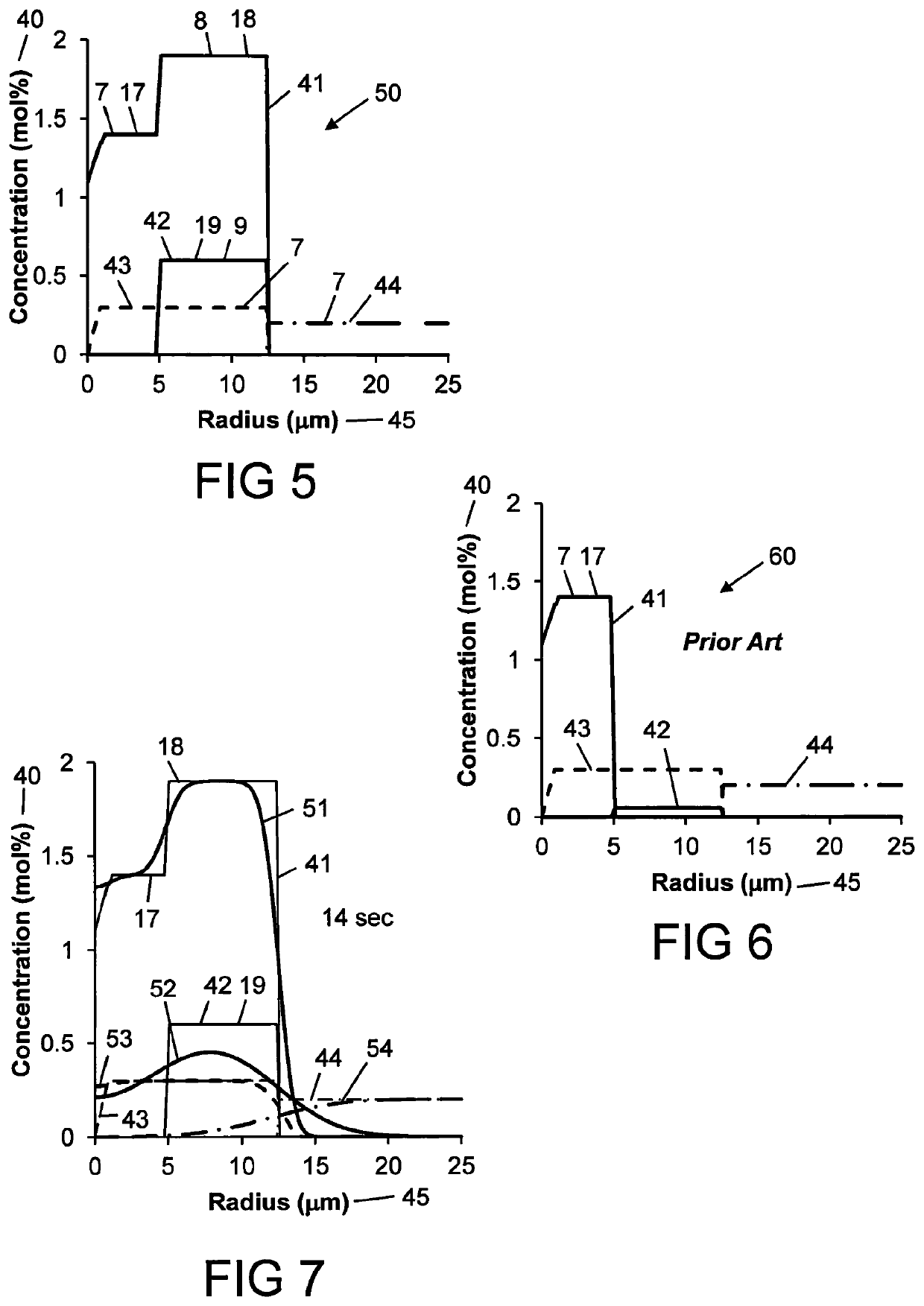
[0161]FIG. 5 shows dopant concentration 40 in mole percent versus radius 45 in microns for an optical fibre 50. The optical fibre 50 is an example of the optical fibre 10 of FIG. 1. The first dopant 7 and the concealed dopant 8 both comprise germania. The first dopant 7 also includes phosphorus and chlorine. The germania concentration 41 had the first dopant concentration 17 in the core 1, and the concealed dopant concentration 18 in the doped area 2, which concealed dopant concentration 18 was larger than the first dopant concentration 17. The cross-sectional area containing the concealed dopant 8 is more than five times the cross sectional area of the core 1. Similar designs have cross sectional areas containing the concealed dopant 8 that is at least two times greater than the cross sectional area of the core 1, and can be as large as ten times greater. The mobile dopant 9 was fluorine. The fluorine concentration 42 had a mobile dopant concentration 19 in the doped area 2. The cl...
example 2
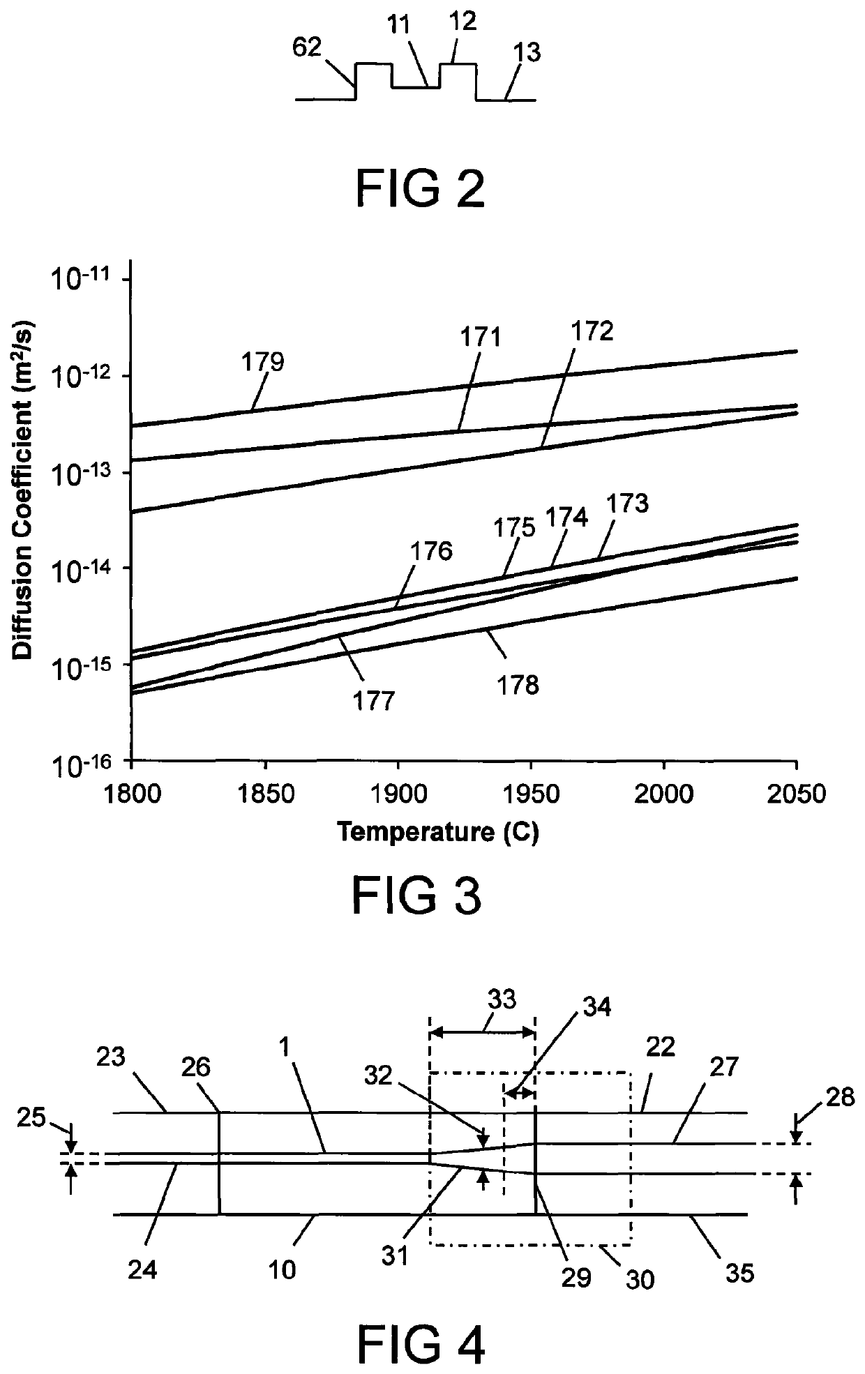
[0185]Referring again to FIG. 4, the second optical fibre 22 used in this example was a passive optical fibre 180 shown in FIG. 18. The optical fibre 10 was the optical fibre 50 of FIGS. 5 and 12 and Example 1. The optical fibre 180 had the core diameter 28 equal to approximately 25 μm. The optical fibre 180 was a passive fibre comprising no rare-earth dopant. The core 27 was doped with germania, resulting in a core comprising germanium doped silica.
[0186]FIG. 18 shows the measured refractive index profiles (RIP) 134 before heating (dashed line) of the optical fibre 180. The core 27 includes a refractive index dip 137 at the centre, which dip is typical of optical fibres made from modified chemical vapour deposition (MCVD). The measured refractive index profile 135 was measured at 25 C after heating (solid line) to 2050 C for 14 seconds. The refractive index profiles 134 and 135 are very similar indicating that there is significantly less diffusion occurring in the optical fibre 180...
example 3
[0190]FIG. 22 shows a design of an optical fibre 220 that is similar to the optical fibre 50 of FIG. 5, but where the fluorine concentration 42 has been increased from 0.6 mol % to 1 mol %. The germania concentration 41 in the doped region 2 was increased to offset the depression in the refractive index 5 induced by the fluorine. The germania concentration 41 was 3.55 mol % in the doped region 2, and 1.75 mol % in the core 1, which corresponds to a concentration ratio of the concealed dopant (germania) concentration 18 in the doped area 2 to the first dopant concentration 17 of the first dopant 7 (germania) in the core 1 of approximately two.
[0191]FIGS. 23 to 25 show the calculated germania concentration 51, fluorine concentration 52, phosphorus pentoxide concentration 53, and chlorine concentration 54 after diffusing at a temperature of 2050 C for 7, 9, 14 seconds respectively. The initial fluorine concentration 41 was zero in the core 1. The amount of fluorine diffusing out of the...
PUM
 Abstract
Description
Claims
Application Information
 - R&D
- Intellectual Property
- Life Sciences
- Materials
- Tech Scout
- Unparalleled Data Quality
- Higher Quality Content
- 60% Fewer Hallucinations
Browse by: Latest US Patents, China's latest patents, Technical Efficacy Thesaurus, Application Domain, Technology Topic, Popular Technical Reports.
© 2025 PatSnap. All rights reserved.Legal|Privacy policy|Modern Slavery Act Transparency Statement|Sitemap|About US| Contact US: help@patsnap.com


