Optical Connector

a technology of optical fiber cables and connectors, applied in the field of optical connectors, can solve problems such as increasing the loss of connection, and achieve the effects of reducing the loss of connection

Inactive Publication Date: 2009-10-01
HOSIDEN CORP
View PDF9 Cites 9 Cited by
  • Summary
  • Abstract
  • Description
  • Claims
  • Application Information

AI Technical Summary

Benefits of technology

[0024]With the configuration described above, the optical connector of the present invention is capable of ensuring a sufficient pull-out strength of the optical fiber cable to prevent the optical fiber cable from being pulled out of the optical connector when the optical fiber cable is pulled. In addition, the ferrule is not excessively displaced. Therefore, the problem can be prevented that the spring that presses the ferrule is plastically deformed by an excessive displacement of the ferrule and the pressure strength of the spring that biases the ferrule forward (toward the receptacle cylinder) is reduced to impair optical characteristics. Accordingly, stable optical characteristics can be obtained.
[0025]The stoppers for ensuring the pull-out strength are integral parts of the spring that presses the ferrule. Therefore, the number of parts and the number of assembly steps are not increased and consequently the optical connector can be fabricated at low costs.

Problems solved by technology

In addition, if the optical fiber excessively moves in the direction of the axis of the optical fiber when the optical fiber is pulled, connection loss increases.

Method used


Image

  • Optical Connector
  • Optical Connector
  • Optical Connector

Examples


Embodiment Construction

[0035]An embodiment of the present invention will be described below.

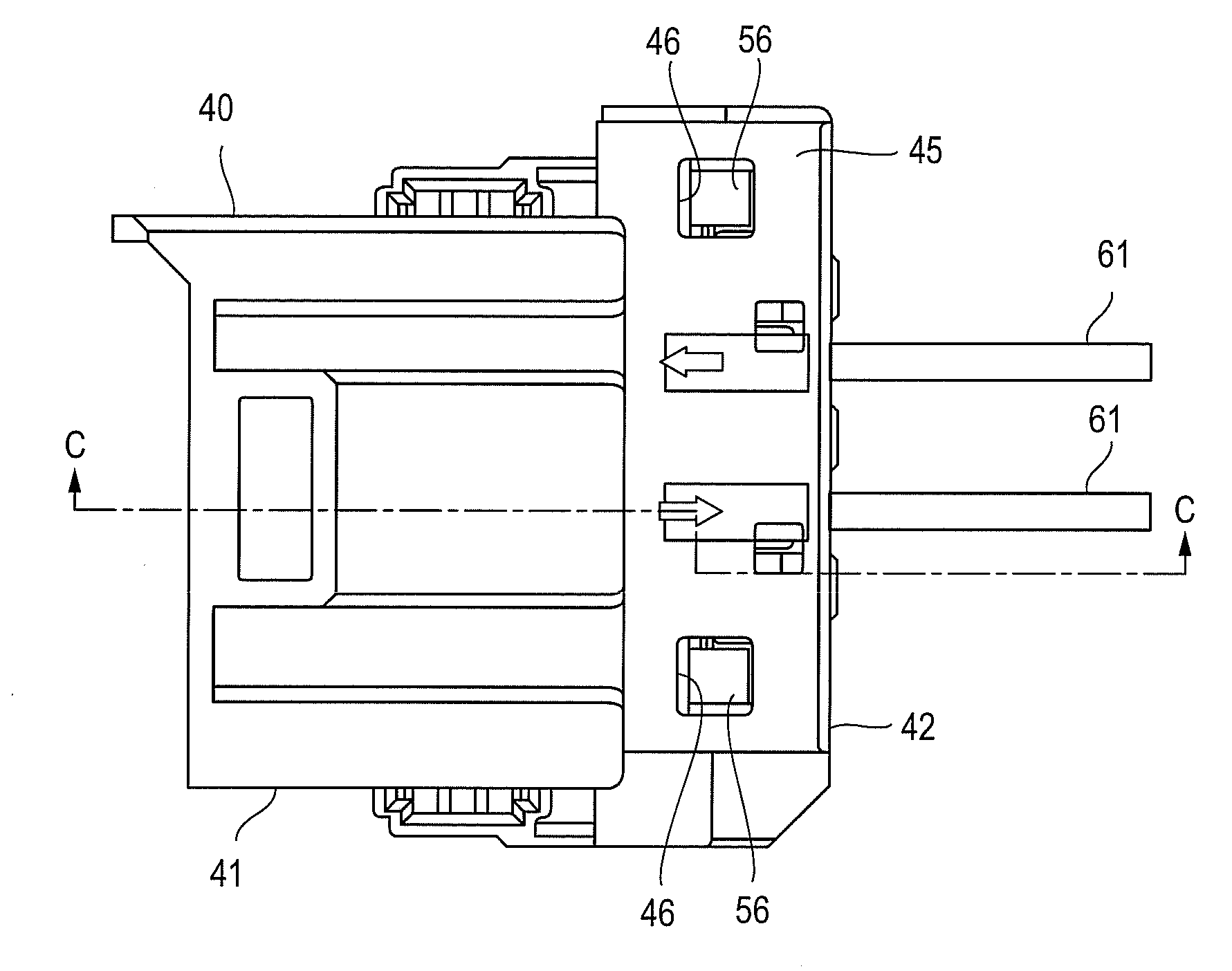
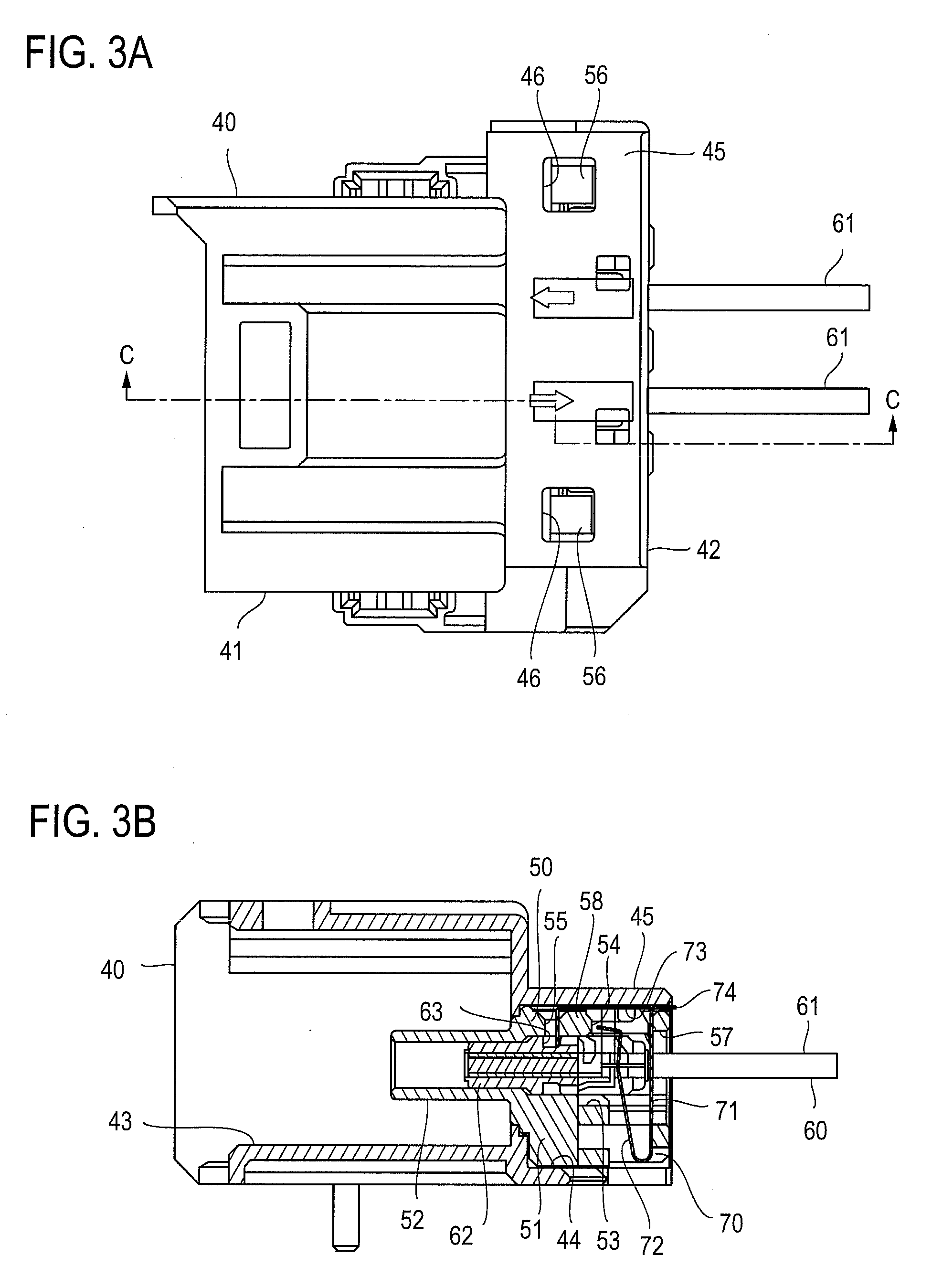
[0036]FIG. 3A shows an exterior view of an optical connector according to the present invention. FIGS. 3B, 4, and 5A show a cross section structure of the optical connector. FIG. 6 shows the optical connector disassembled into components. In the example, the optical connector includes a receptacle body 40, pigtail body 50, a pair of ferrule assemblies 60, and a spring 70. FIG. 7 shows the spring 70 enlarged.

[0037]A configuration of each of the components will be described first.

[0038]The receptacle body 40 is made of a resin and includes a front box-like part 41 and a rear box-like part 42 which is connected to the front box-like part and has a height lower than the front box-like part 41. A front opening 43 is formed in the front box-like part 41, into which another optical connector is to be inserted and fit. A chamber 44 opened backward is formed in the rear box-like part 42. The chamber 44 internally communicat...


PUM


Abstract

An optical connector includes a receptacle body 40 having an engage hole 46 formed in a peripheral wall 45 of a chamber 44, a pigtail body 50 having a base body 51 contained in the chamber 44 and a locking protrusion 56 engaged in the engage hole 46 to attach the pigtail body 50, and a ferrule assembly 60 being inserted in a container 53 in the base body 51 so that the ferrule 62 is positioned in a receptacle cylinder 52, and a spring 70 inserted through an opening 54 in the base body 51 and pressing the ferrule 62 forward, wherein a stopper 73 is formed in the spring 70 as an integral part of the spring 70. A locking part 73b included in the stopper 73 is positioned in a recess 63 in the ferrule 62.

Description

BACKGROUND ART[0001]The present invention relates to an optical connector used in an in-vehicle LAN, for example, and, in particular, to an optical connector holding a terminal of an optical fiber cable.[0002]FIG. 1 shows a configuration of an optical connector described in Japanese Patent Application Laid Open No. 2002-131584 (filed on May 9, 2002, hereinafter referred to as Document 1), which is one example of a conventional optical connector of this type. In FIG. 1, reference numeral 11 denotes a housing, 12 denotes a stopper, and 13 denotes an optical fiber cord. The optical fiber cord 13 in this example has a first cladding 13b around the perimeter of an optical fiber 13a and a second cladding 13c around the perimeter of the first cladding 13b. [0003]A cord hole 14 for containing the optical fiber cord 13 is formed in the housing 11. An opening 15 is formed on one side of the cord hole 14 for allowing the cord hole 14 to communicate with the exterior. A ferrule 16 holding the o...

Claims


Application Information

Patent Timeline
Patent Type & Authority Applications(United States)
IPC IPC(8): G02B6/36
CPCG02B6/3869G02B6/4292G02B6/3887G02B6/3879G02B6/3888G02B6/36G02B6/38
Inventor NAKAGAWA, HIROSHIISODA, TAKESHI
Owner HOSIDEN CORP
Why Eureka
Try Eureka