Polishing platen and polishing apparatus

Inactive Publication Date: 2009-10-01
EBARA CORP
View PDF7 Cites 21 Cited by
  • Summary
  • Abstract
  • Description
  • Claims
  • Application Information

AI Technical Summary

Benefits of technology

[0016]According to one aspect of the present invention described above, because the upper surface of the polishing platen comprises the combination of the first surface and the second surface having a surface roughness which is different from that of the first surface, the removal forces required are different at the first and second surfaces. Thus, the removal force is changed when removing the polishing pad, compared with the case where the upper surface of the polishing platen comprises a uniform surface having the same surface roughness in its entirety, e.g., a mirror-finished surface. Accordingly, the polishing pad can be relatively easily removed from the upper surface of the polishing platen.
[0017]According to another aspect of the present invention described above, because the upper surface of the polishing platen comprises the combination of at least one mirror surface portion and at least one rough surface portion, a large force is not required for removing the polishing pad, compared with the case where the upper surface of the polishing platen comprises the mirror-finished surface in its entirety, and hence the polishing pad can be relatively easily removed.
[0018]According to another aspect of the present invention described above, becau

Problems solved by technology

The polishing apparatus having the above structures has a problem in that, when replacing the polishing pad 16 with new one, a large force is required for

Method used


Image

  • Polishing platen and polishing apparatus
  • Polishing platen and polishing apparatus
  • Polishing platen and polishing apparatus

Examples


Embodiment Construction

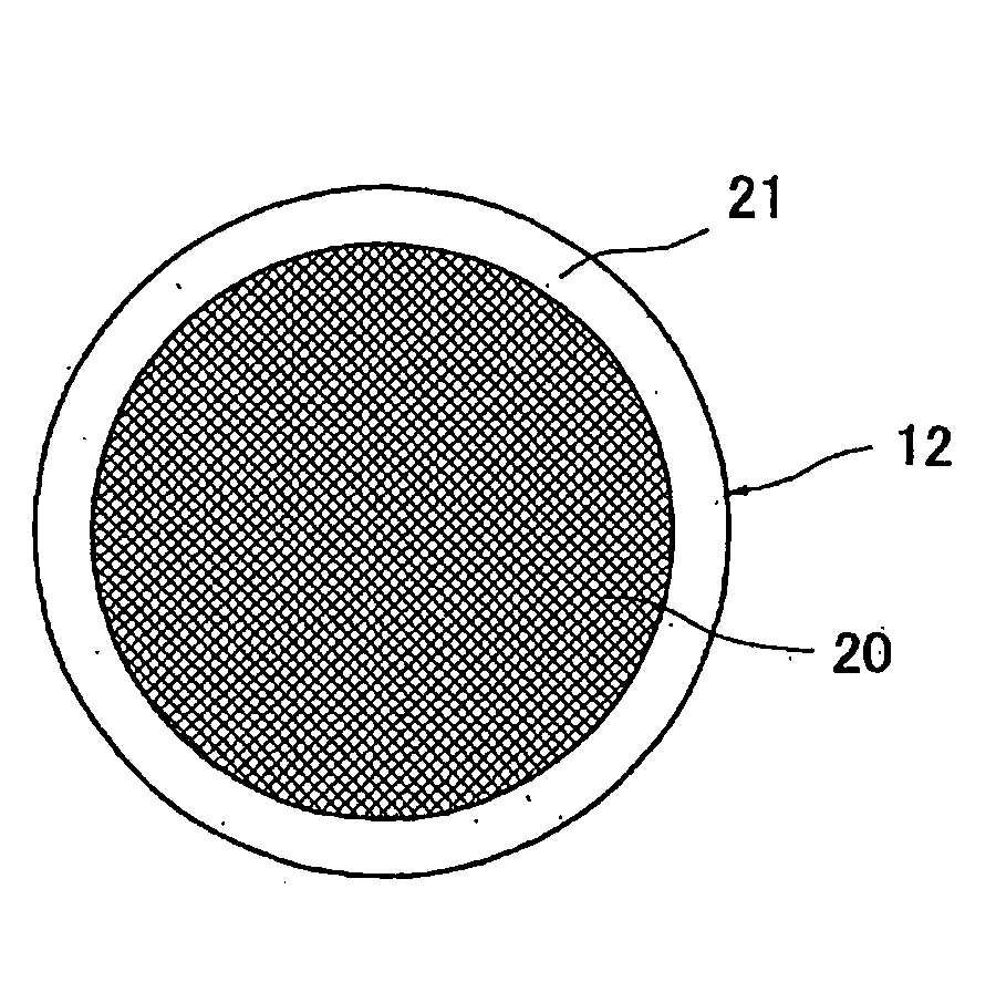
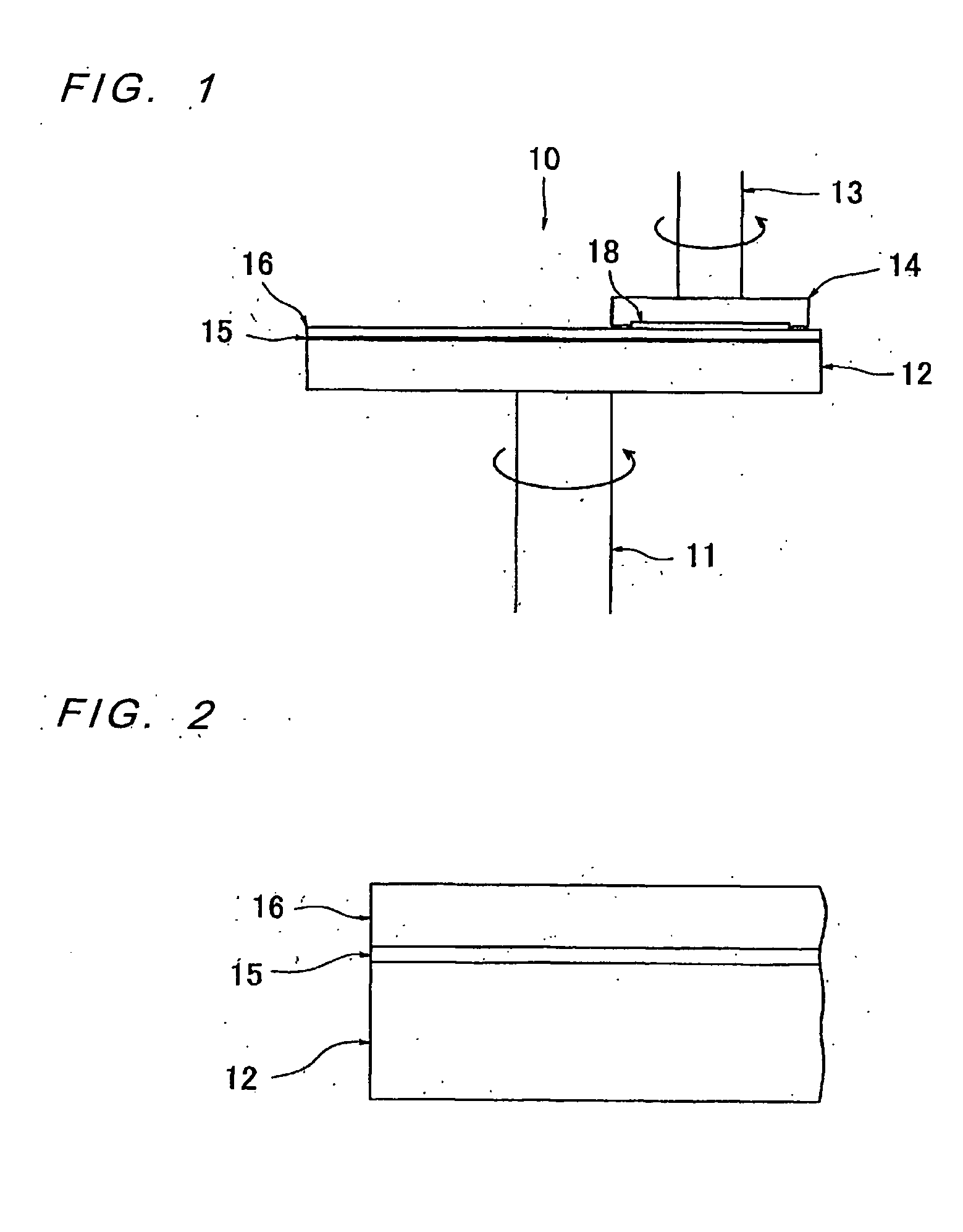
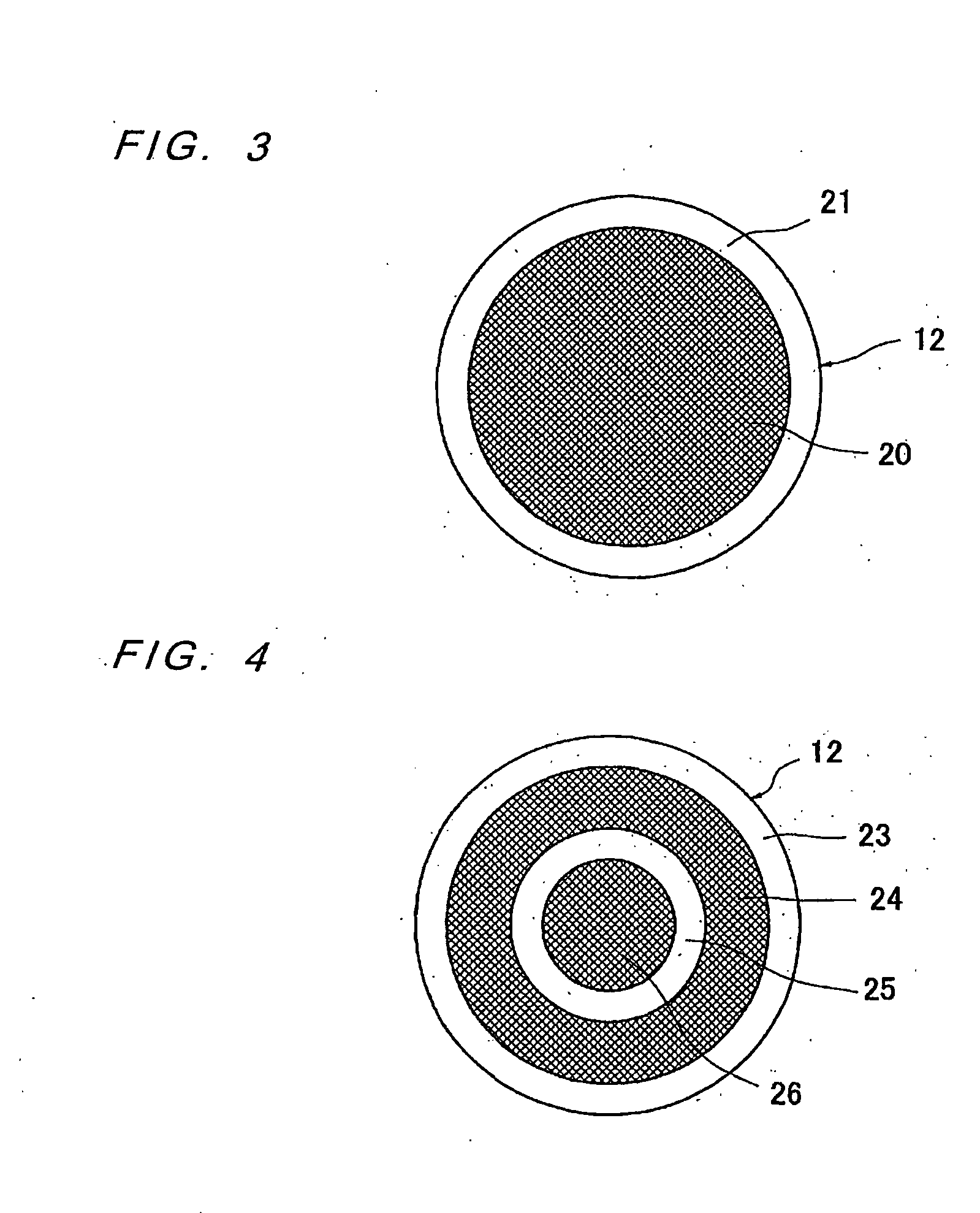
[0030]Embodiments of the present invention will be described below with reference to the drawings. FIG. 3 is a plan view showing a structural example of an upper surface of a polishing platen of a polishing apparatus according to the present invention. As shown in the drawing, an upper surface of a polishing platen 12 comprises a circular rough surface portion 20 which is a grained surface at a center thereof, and a belt-shaped mirror surface portion 21 which is a mirror-finished surface arranged around the rough surface portion 20.

[0031]A rear surface of a polishing pad 16 is attached to the upper surface of the polishing platen 12 with an adhesive (e.g., adhesive tape) 15. With this structure, the belt-shaped mirror surface portion 21 provides a strong adhesive area, but the circular rough surface portion 20 provides a weak adhesive area. Thus, when an operation of removing the polishing pad 16 is started from its edge portion, i.e., a peripheral portion of the mirror surface port...


PUM


Abstract

The present invention provides a polishing platen which does not require a large force for removing a polishing pad from an upper surface of the polishing platen and can thus make it relatively easy to remove the polishing pad therefrom. The present invention also provides a polishing apparatus having such polishing platen. The polishing platen (12) according to the present invention includes a surface to which a polishing pad is attached. The surface of the polishing platen (12) includes a combination of a first surface (20) and a second surface (21) having a surface roughness which is different from that of the first surface (20).

Description

TECHNICAL FIELD[0001]The present invention relates to a polishing platen for polishing a substrate, such as a semiconductor wafer, and a polishing apparatus using such a polishing platen, and more particularly to a polishing platen having an upper surface from which a polishing pad, attached thereto, can be easily removed, and to a polishing apparatus using such a polishing platen.BACKGROUND ART[0002]A CMP apparatus (chemical mechanical polishing apparatus) is known as an apparatus for polishing a substrate, e.g., a semiconductor wafer. As shown in FIGS. 1 and 2, a polishing apparatus 10 comprises a polishing platen 12 rotatable about a rotating shaft 11, and a substrate holding head 14 rotatable about a rotating shaft 13. A polishing pad 16 is attached to an upper surface of the polishing platen 12 with an adhesive (e.g., adhesive tape) 15. The substrate holding head 14 is operable to hold and rotate a substrate 18, such as a semiconductor wafer, and press the substrate 18 against ...

Claims


Application Information

Patent Timeline
IPC IPC(8): B24B37/04B24B41/00B24B37/12H01L21/304
CPCB24B37/16B24B37/04H01L21/304
Inventor KOBAYASHI, TAKUJIAIZAWA, HIDEOUMEMOTO, MASAOSONE, TADAKAZUTORII, HIROOMITAKAHASHI, NOBUYUKITSUZUKI, TAKASHI
Owner EBARA CORP
Why Eureka
Try Eureka