Disk array device

a technology of array devices and disks, applied in the field of disk array devices, can solve the problems of large amount of battery consumption (backup power), limited physical size and cost of battery capacity mounted on a device, and long time required for a backup time, so as to achieve small battery capacity, longer blackout time, and large battery capacity

Inactive Publication Date: 2009-10-01
HITACHI LTD
View PDF20 Cites 23 Cited by
  • Summary
  • Abstract
  • Description
  • Claims
  • Application Information

AI Technical Summary

Benefits of technology

[0013]As for “a”, in the first method, the battery capacity is large (disadvantageous), meanwhile in the second method, the battery capacity is small (advantageous). In the first method, as described above, a longer blackout time requires a larger battery capacity. In the second method, even in a case of the long-time blackout, since a constant power is enough to supply the power to the memory and the like, the battery capacity can be small.
[0014]As for “b”, the re

Problems solved by technology

However, the battery capacity mounted on a device has a limitation in aspects of physical size and costs.
However, in the first method, when the long-time blackout occurs, a long time is required for a backup time.
Therefore, an amount of battery consumption (backup power) becomes large.
Accordingly, the battery capacity to be mounted on a device becomes large, and thereby not meeting the demand for reducing the battery capacity.
Also, when the battery capacity mounted on a device is reduced, an insufficient amount of the battery may cause a power failure on the main memory, and result in destruction of data.
Therefore, there is a disadvantage in an aspect of data integrity.
Also, s

Method used


Image

  • Disk array device
  • Disk array device
  • Disk array device

Examples


Embodiment Construction

[0055]

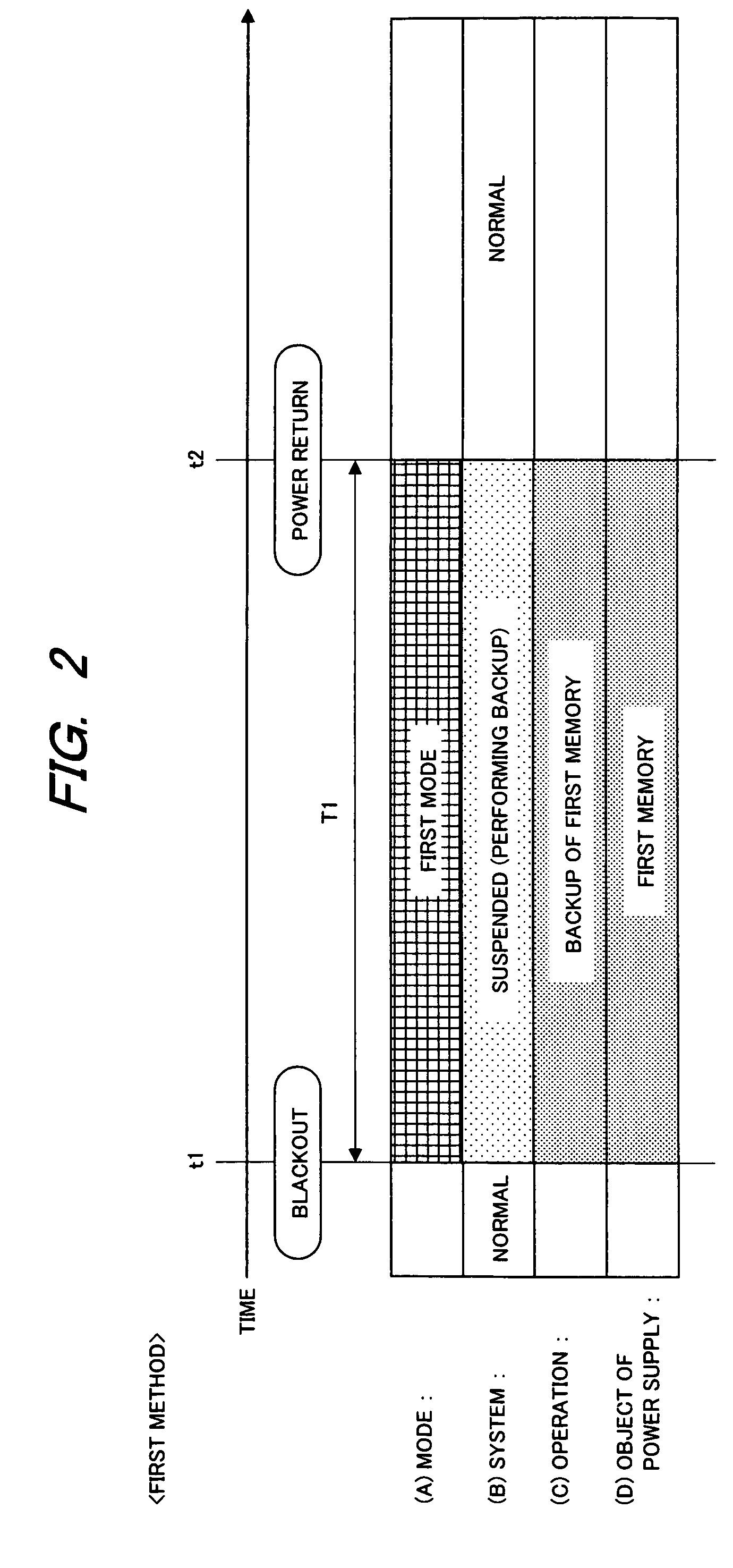
[0056]First of all, conventional technologies (first method and second method), which are used as a prerequisite art in the present embodiment, will be described with reference to FIGS. 1 to 3. Contents of the conventional arts are the basically same as that of the present embodiment.

[0057]

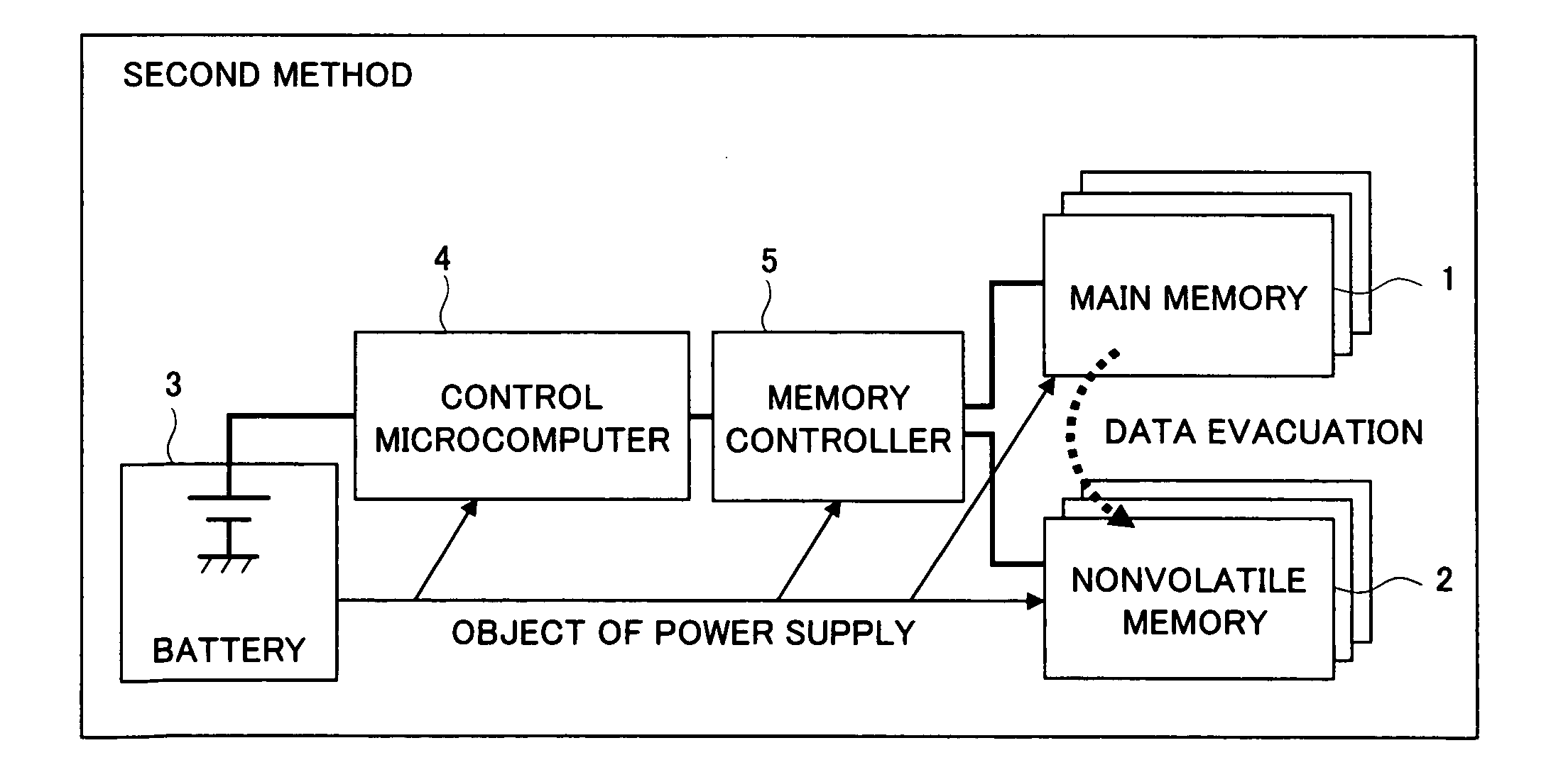
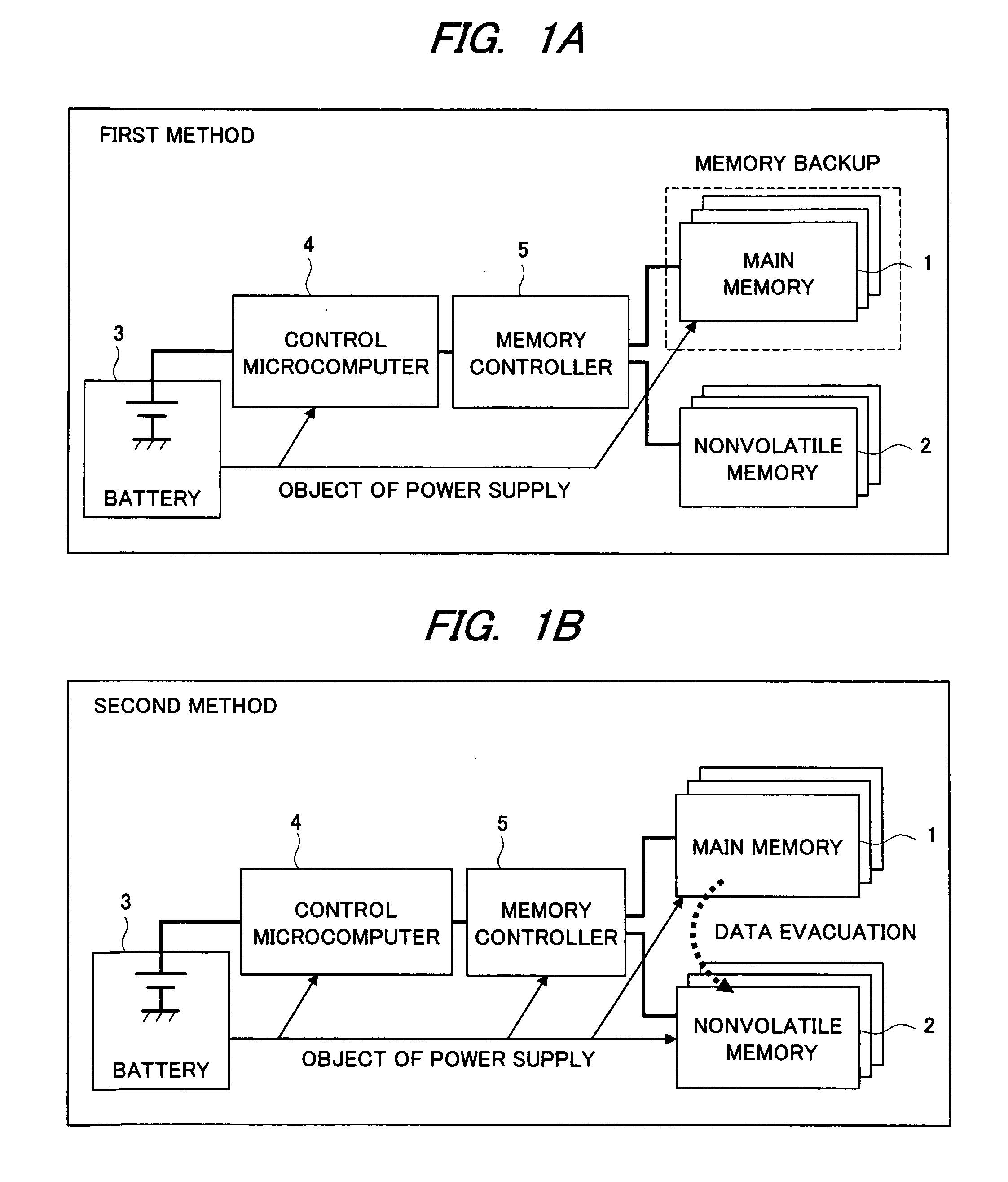
[0058]FIG. 1A shows a block configuration of a device according to the first method (“memory backup method”). The configuration of the disk array device includes a main memory (first memory) 1, a nonvolatile memory (second memory) 2, a battery 3, a control microcomputer 4, and a memory controller 5. The control microcomputer 4 is connected with the main memory 1 and the nonvolatile memory 2 via the memory controller 5. The control microcomputer 4 and the like are connected with the battery 3, and the power can be supplied (discharge) to the respective components from the battery 3.

[0059]The control microcomputer 4 controls the entire system including the memory controller 5 and the like. The...


PUM


Abstract

In control of the disk array device (backup system), when a blackout occurs, the disk array device is first operated in a first method to backed up a main memory by using a power supply from a battery. During the first method, a blackout continuous time and the like are integrated, and at a timing in which the integrated value satisfies a condition, the first method is then shifted to the second method to evacuate data from the main memory onto a nonvolatile memory based on a power supply.

Description

CROSS-REFERENCE TO RELATED APPLICATION[0001]The present application claims priority from Japanese Patent Application No. JP 2008-082957 filed on Mar. 27, 2008, the content of which is hereby incorporated by reference into this application.TECHNICAL FIELD OF THE INVENTION[0002]The present invention relates to a disk array device (storage device) and a backup method; in particular, to a backup method of data on a memory by using a battery at a time of an occurrence of blackout / power return.BACKGROUND OF THE INVENTION[0003]As a backup method of data in a volatile memory (main memory) in a controller of a conventional disk array device (hereinafter, simply referred to as a device (system)), there are a first method (FIG. 1A) and a second method (FIG. 1B) as described below.[0004](1) In the first method (“memory backup method”), when a blackout occurs, by using a battery, a power is supplied to a memory from the battery to retain data in the memory by a refresh operation or the like. In ...

Claims


Application Information

Patent Timeline
IPC IPC(8): G06F12/16
CPCG06F11/1441G06F1/30
Inventor HOSAKA, FUMIAKI
Owner HITACHI LTD
Why Eureka
Try Eureka