
System and Method for Determining Air Density Based on Temperature Sensor Data

a temperature sensor and air density technology, applied in the direction of electrical apparatus construction details, instruments, specific gravity measurements, etc., can solve the problems of accelerated wear on the fans, excessive noise, waste of energy, etc., and achieve the effect of constant processor load

Active Publication Date: 2009-10-08
LENOVO GLOBAL TECH INT LTD
View PDF29 Cites 27 Cited by
  • Summary
  • Abstract
  • Description
  • Claims
  • Application Information

AI Technical Summary

Benefits of technology

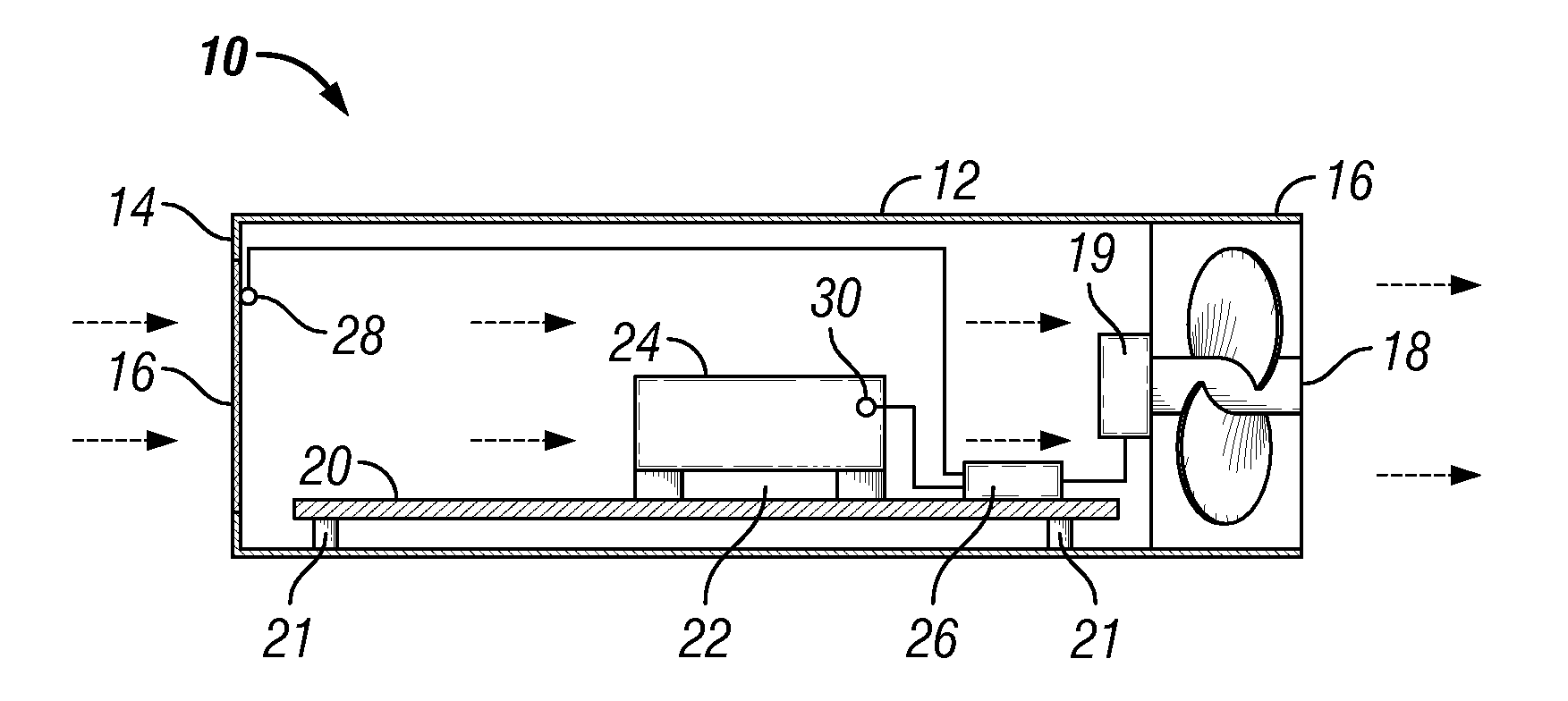
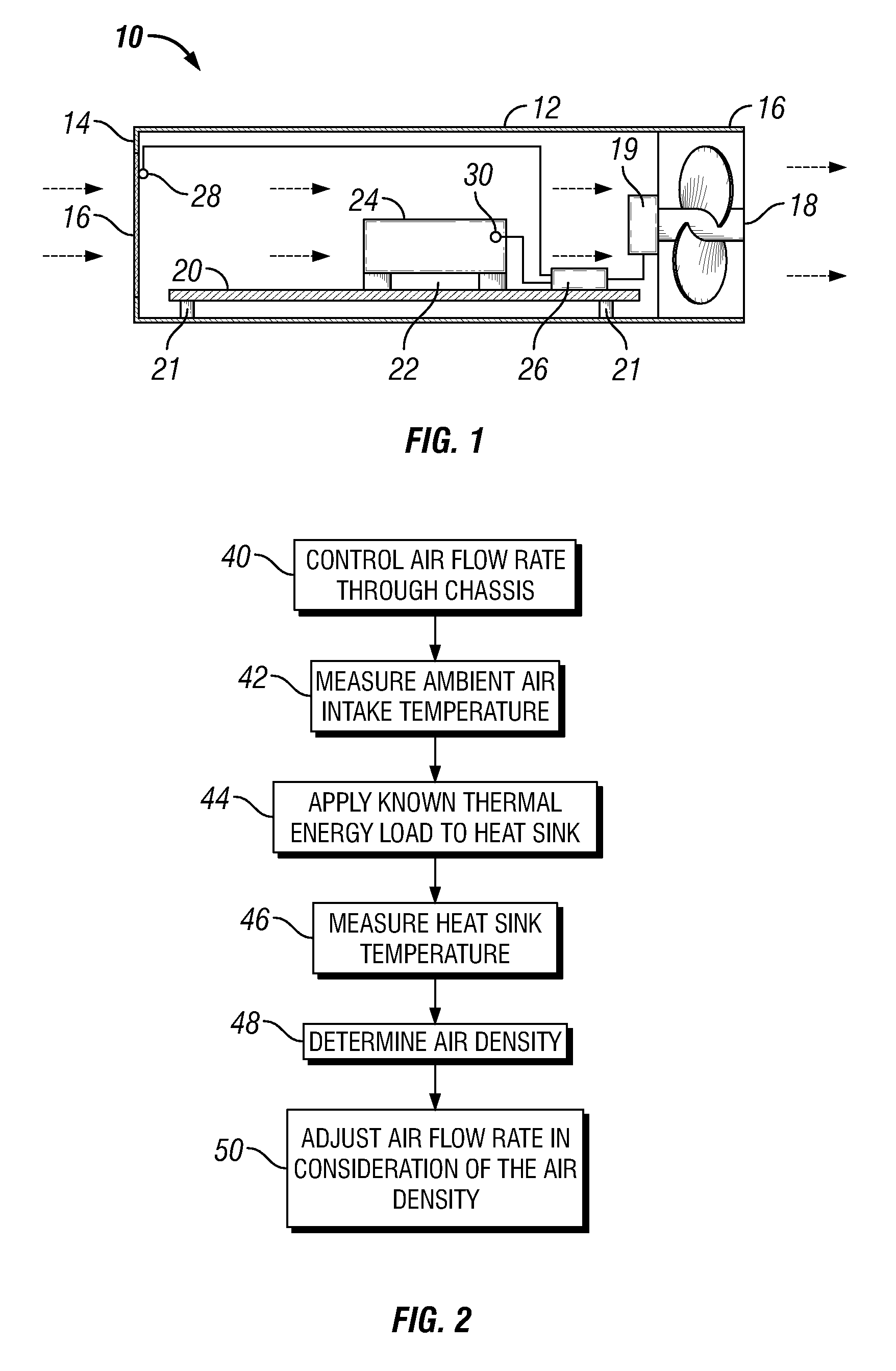
The invention provides a method for measuring air density in a computer chassis by inducing air flow through a fan and measuring the temperature of the air at the intake and the heat sink. The air density is determined based on the air flow rate and the difference between the intake air temperature and the heat sink temperature, and the fan speed is adjusted accordingly. This allows for better control of air flow and temperature in the computer chassis. The invention also includes a computer system with a fan, ambient air temperature sensor, heat-generating device, heat sink, and controller that controls the fan speed based on the difference between the intake air temperature and the heat sink temperature while the heat-generating device is in use.

Problems solved by technology

Consequently, these fans run faster than necessary at lower altitudes, resulting in a waste of energy, excessive noise and accelerated wear on the fans.
Although this mode of operation is simple, it does not address the demands placed on modern computer systems.
One problem with such a solution is that many electronic systems, such as rack-based computer systems, have many different components or subsystems, each requiring its own cooling fan.
Equipping each component or subsystem with a dedicated on-board altimeter could significantly increase the cost of the electronic system as a whole.
System reliability and maintenance might also suffer because each altimeter is subject to potential failure.
Still further, the rising prevalence of notebook computers means that user-input altitude is unworkable.
Current altitude information may be particularly important for a notebook computer, since unnecessary high fan speeds will drain the batteries.

Method used


Image

  • System and Method for Determining Air Density Based on Temperature Sensor Data
  • System and Method for Determining Air Density Based on Temperature Sensor Data
  • System and Method for Determining Air Density Based on Temperature Sensor Data

Examples


Embodiment Construction

[0014]One embodiment of the present invention provides a method for measuring air density. As used herein, air density, air pressure and altitude are each considered to be interrelated conditions that may substitute for the others, such that measuring or determining one of these conditions enables the determination of the other interrelated conditions. The present disclosure focuses on air density as the condition that is more relevant to heat transfer and as the condition that is more fundamental to the measurements of the embodiments described.

[0015]An embodiment of the method includes inducing air flow through a computer chassis at a known air flow rate, and measuring the temperature of the air at an air intake to the computer chassis. A known amount of thermal energy is then applied to a heat sink disposed within the chassis. Measuring the temperature of the heat sink under these conditions enables the determination of air density as a function of the air flow rate and the diffe...


PUM

PropertyMeasurementUnit
air densityaaaaaaaaaa
air flow rateaaaaaaaaaa
temperatureaaaaaaaaaa

Abstract

A computer system and method for measuring air density in a computer chassis. The computer chassis includes a fan, an ambient air temperature sensor, and a heat-generating device with a heat sink, a heat sink temperature sensor, and a controller. The controller controls the fan speed and applies a known amount of thermal energy to the heat sink, then determines the air density from the difference in temperature between the ambient air and the heat sink. The controller may then use the air density determination to adjust the air flow rate through the computer chassis to provide a proper air flow rate for cooling.

Description

BACKGROUND OF THE INVENTION[0001]1. Field of the Invention[0002]The present invention relates to the determination of air density for use in controlling the cooling of electronic systems, such as computers.[0003]2. Description of the Related Art[0004]Cooling fans are commonly used to cool electronic devices, such as computers. For example, on-board cooling fans are installed in individual computer servers, and blower modules are often included within multi-blade chassis or enclosures to cool multiple blade servers housed in the chassis. It is recognized in the design of air cooling systems that air density decreases with increasing altitude, and that lower air density requires greater volumes of air flow to achieve an equivalent level of cooling.[0005]Some cooling fans are operated at a single-speed that is fast enough to achieve the desired air flow and cooling at any altitude. Consequently, these fans run faster than necessary at lower altitudes, resulting in a waste of energy, ex...

Claims


Application Information

Patent Timeline
Patent Type & Authority Applications(United States)
IPC IPC(8): H05K7/20G01N9/36
CPCG06F1/20H05K7/20209G06F1/206
Inventor GLOVER, TROY WILLIAMSJUNE, MICHAEL SEANSCOTT, III, WHITCOMB RANDOLPHSMITH, ROBERT SALGUERO
Owner LENOVO GLOBAL TECH INT LTD
Learn More